Control method of PFC circuit

A control method and circuit technology, applied in the field of power supply, can solve problems such as difficulty in adapting to PFC topology and implementation difficulties, and achieve the effects of easy implementation, improved efficiency, and reduced turn-on loss

Active Publication Date: 2018-05-25
VERTIV CORP
View PDF6 Cites 9 Cited by
  • Summary
  • Abstract
  • Description
  • Claims
  • Application Information

AI Technical Summary

Problems solved by technology

However, the control method of the PFC circuit in the prior art is usually difficult to implement, and it is difficult to adapt to the unreasonable PFC topology

Method used


Image

  • Control method of PFC circuit
  • Control method of PFC circuit
  • Control method of PFC circuit

Examples


Embodiment Construction

[0054] In order to make the object, technical solution and advantages of the present invention clearer, the present invention will be further described in detail below in conjunction with the accompanying drawings and embodiments. It should be understood that the specific embodiments described here are only used to explain the present invention, not to limit the present invention.

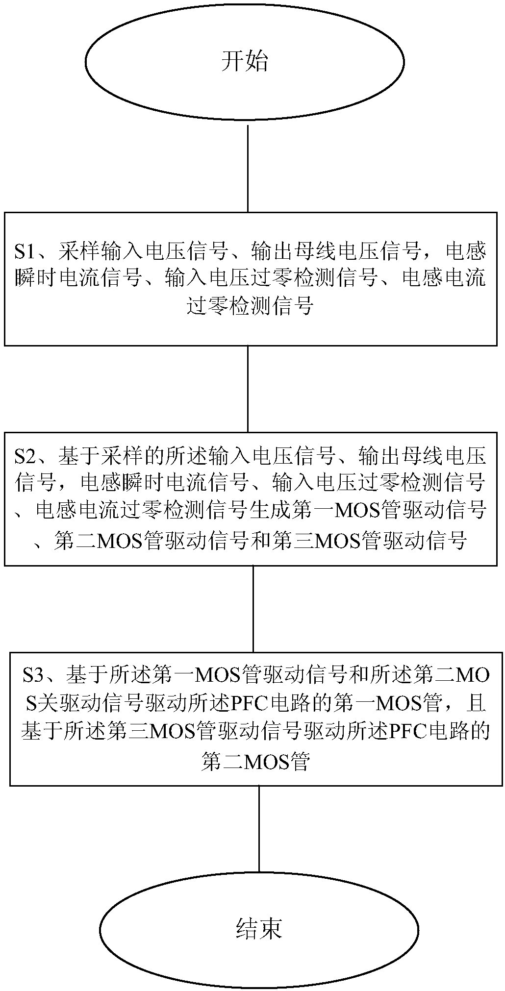
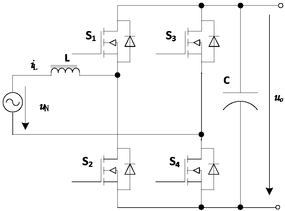
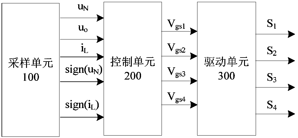
[0055] figure 2 is the circuit schematic diagram of the totem pole PFC circuit. Such as figure 2 As shown, the dual-phase totem pole PFC circuit includes a PFC inductor L, high frequency MOS transistors S1, S2, power frequency MOS transistors S3, S4 and an output capacitor C. figure 1 is a flowchart of the control method of the PFC circuit according to the first embodiment of the present invention. image 3 yes figure 1 The control method shown in the PFC circuit controls the figure 2 Schematic diagram of the control logic of the PFC circuit shown.

[0056] The control method of the PFC circ...


PUM


Abstract

A control method of a PFC circuit comprises that S1) an input voltage signal, an output bus voltage signal, an inductance instant current signal, an input voltage zero-crossing detection signal and aninductance current zero-crossing detection signal are sampled; S2) on the basis of the sampled input voltage signal, output bus voltage signal, inductance instant current signal, input voltage zero-crossing detection signal and inductance current zero-crossing detection signal, first, second and third MOS driving signals are generated; and S3) a first MOS of the PFC circuit is driven on the basisof the first and second MOS driving signals, and a second MOS of the PFC circuit is driven on the basis of the third MOS driving signal. The control method of the PFC circuit is easy to realize and can adapt to different PFC topologies.

Description

technical field [0001] The present invention relates to the field of power supplies, and more specifically, to a control method for a power factor correction (Power FactorCorrection, PFC) circuit. Background technique [0002] At present, in the design of high-efficiency power module PFC circuit design has generally not used the traditional bridge PFC, replaced by bridgeless PFC, such as dual boost bridgeless PFC topology, H-bridge PFC topology, and totem pole (Totem pole) PFC topology . With the pursuit of higher efficiency, it is not enough to just eliminate the rectifier bridge from the topology and replace the rectifier diode with a MOS tube. It is also necessary to realize the zero voltage switch (Zero Voltage Switch, ZVS) of the MOS tube, so that Turn-on loss is reduced and efficiency is improved. However, the control method of the PFC circuit in the prior art is usually difficult to implement, and it is difficult to adapt to unreasonable PFC topologies. Contents of...

Claims


Application Information

Patent Timeline
Patent Type & Authority Applications(China)
IPC IPC(8): H02M1/42
CPCH02M1/4233Y02B70/10
Inventor 刘慧
Owner VERTIV CORP
Why Eureka
Try Eureka