Dual-cavity self-thermal-insulation wall system obtained by splicing small jointed boards

A self-insulation and splicing technology, which is applied in the direction of thermal insulation, building thermal insulation materials, walls, etc., can solve the problems of inability to achieve self-insulation of walls and large floor space, save materials, reduce floor space, and achieve good thermal insulation performance. Effect

Inactive Publication Date: 2018-05-29
DALIAN GAOMA ART DESIGN ENG
View PDF4 Cites 0 Cited by
  • Summary
  • Abstract
  • Description
  • Claims
  • Application Information

AI Technical Summary

Problems solved by technology

[0002] At present, the insulation of the wall is the basis for realizing building energy saving. Generally, the insulation layer needs to be laid on the inner and outer walls of the general wall, and the self-insulation of the wall cannot be realized. The thickness of the outer wall is generally about 360 mm, which occupies a large area. For walls with a double-cavity structure, the panels or blocks used have contact points with the steel structure or wooden frame of the building, so the phenomenon of "thermal bridge" cannot be avoided. The panels used in the existing assembly technology are large in size. , the construction needs large-scale hoisting equipment to complete. Therefore, a building wall that is convenient and quick to install, saves materials, and has good thermal insulation performance is needed. The integration of the double-cavity self-insulation wall system assembled by small pieces of panels can solve the above problems. The wall can replace the block building wall, and can be used as an inner partition wall or an outer protective wall

Method used


Image

  • Dual-cavity self-thermal-insulation wall system obtained by splicing small jointed boards
  • Dual-cavity self-thermal-insulation wall system obtained by splicing small jointed boards
  • Dual-cavity self-thermal-insulation wall system obtained by splicing small jointed boards

Examples


Embodiment Construction

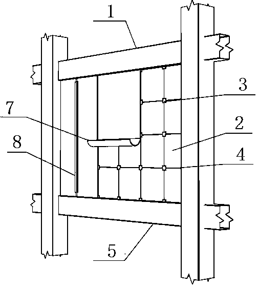
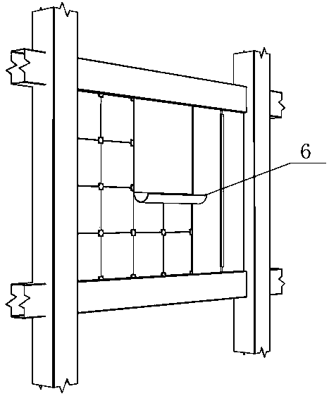
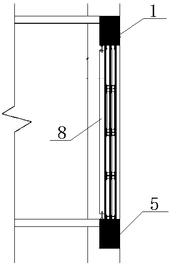
[0015] Such as Figure 1 to Figure 6 As shown, the double-cavity self-insulation wall system assembled by small pieces of panels includes upper beam 1, lower beam 5, connector 3, assembly board 2, cement glue 4 and waterproof layer 6, assembly board 2, connector 3 and The cement glue 4 is assembled together to form the main wall. The upper beam 1 and the lower beam 5 are respectively fixed on the upper and lower ends of the main wall. Leveling ruler, upper and lower beams, several reinforcing steel bars are installed between the upper and lower beams to make the wall more stable, leveling ruler, in the construction process to ensure the smooth splicing of the panels, and the cement glue is applied to the glue grooves and connectors of the panels It is used to fix the jigsaw panels, the connectors are plastic parts, used to insert the steel bars between the upper and lower parts and the three jigsaw panels, and two air layers are separated between the jigsaw panels to form a do...


PUM


Abstract

The invention discloses a dual-cavity self-thermal-insulation wall system obtained by splicing small jointed boards. The system comprises an upper beam, a lower beam, a connecting piece, a splicing plate, cement gel and a waterproof layer; the splicing plate, the connecting piece and the cement gel are jointly spliced into a wall body, the upper beam and the lower beam are fixed to the upper and lower ends of the wall body respectively, and the waterproof layer is laid on the outer wall of the wall body. According to the dual-cavity self-thermal-insulation wall system obtained by splicing thesmall jointed boards, the wall body adopts the small-size jointed boards of the size being 600*600 millimeters, no large hoisting equipment auxiliary assembly is needed, splicing can be suitable for being completed manually, the wall is of a dual-cavity structure, the heat transfer coefficient is quite low and smaller than 0.2, and the heat preservation performance is good; due to the fact that abuilt steel structure frame only makes contact with plastic connecting pieces in wall inner cavities, a thermal bridge is avoided, the wall is only 120 millimeters thick, materials are saved, and thefloor area is decreased.

Description

technical field [0001] The invention relates to a double-chamber self-insulating wall system assembled by small pieces of jigsaw panels. Background technique [0002] At present, the insulation of the wall is the basis for realizing building energy saving. Generally, the insulation layer needs to be laid on the inner and outer walls of the general wall, and the self-insulation of the wall cannot be realized. The thickness of the outer wall is generally about 360 mm, which occupies a large area. For walls with a double-cavity structure, the panels or blocks used have contact points with the steel structure or wooden frame of the building, so the phenomenon of "thermal bridge" cannot be avoided. The panels used in the existing assembly technology are large in size. , the construction needs large-scale hoisting equipment to complete. Therefore, a building wall that is convenient and quick to install, saves materials, and has good thermal insulation performance is needed. The in...

Claims


Application Information

Patent Timeline
Patent Type & Authority Applications(China)
IPC IPC(8): E04B2/56E04B1/76E04B1/66
CPCE04B1/66E04B1/76E04B2/56Y02A30/00Y02B30/90
Inventor 马春东孙秀丽郭磊葛晓扬
Owner DALIAN GAOMA ART DESIGN ENG
Why Eureka
Try Eureka