Air preheater of oscillatory flow type heat pipe, and energy saving drying technique of using the preheater

A technology of oscillating flow heat pipe and air preheater, used in indirect heat exchangers, drying machines, dryers, etc., can solve the problems of large size of waste heat recovery equipment, poor recovery effect, heat waste, etc., to reduce heat The effect of pollution, simple structure and long service life

A technology of oscillating flow heat pipe and air preheater, used in indirect heat exchangers, drying machines, dryers, etc., can solve the problems of large size of waste heat recovery equipment, poor recovery effect, heat waste, etc., to reduce heat The effect of pollution, simple structure and long service life

CN1916546AInactive Publication Date: 2007-02-21SHAN DONG TIAN LI DRYING EQUIP

Image

  • Air preheater of oscillatory flow type heat pipe, and energy saving drying technique of using the preheater
  • Air preheater of oscillatory flow type heat pipe, and energy saving drying technique of using the preheater

Examples


Embodiment

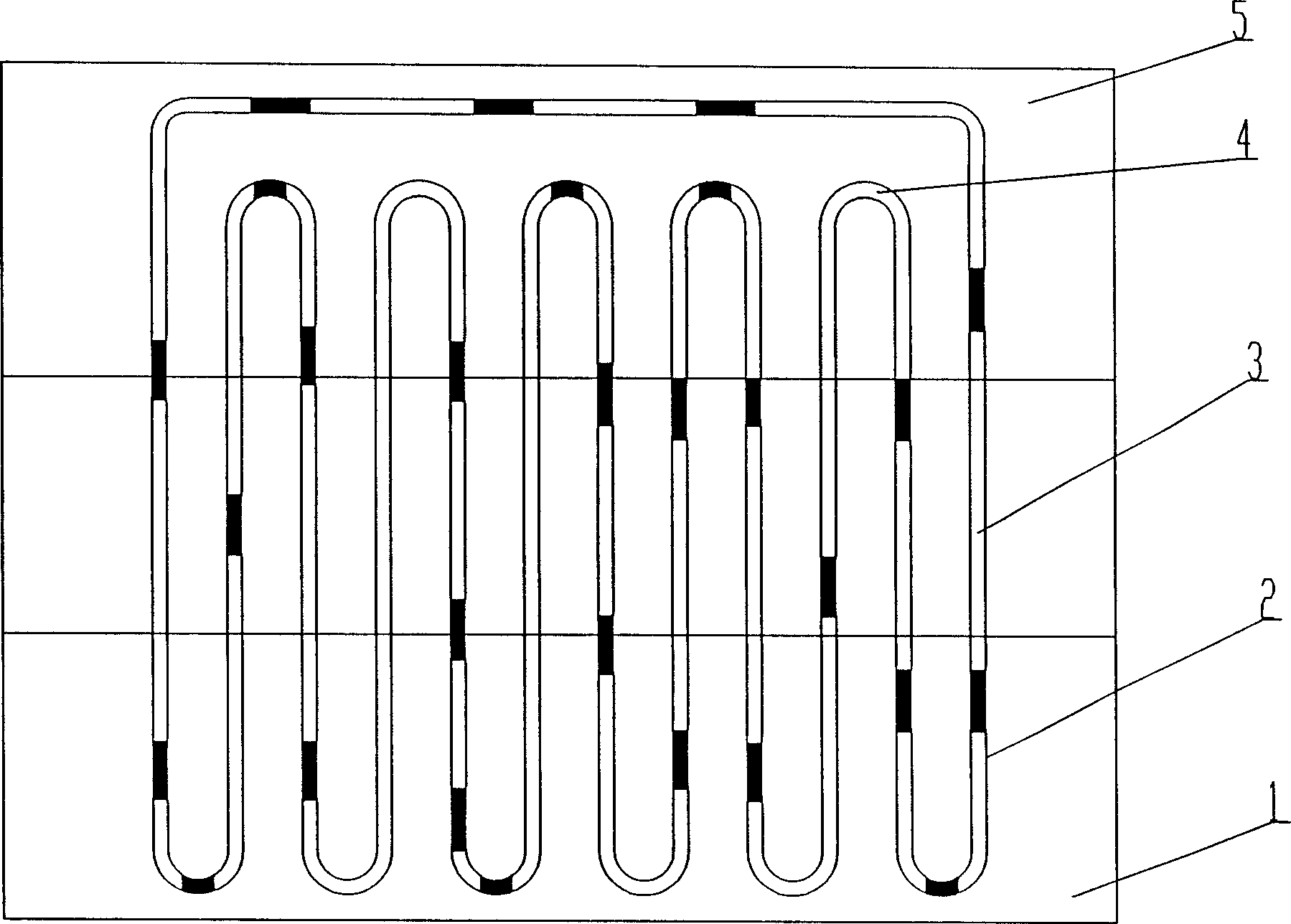
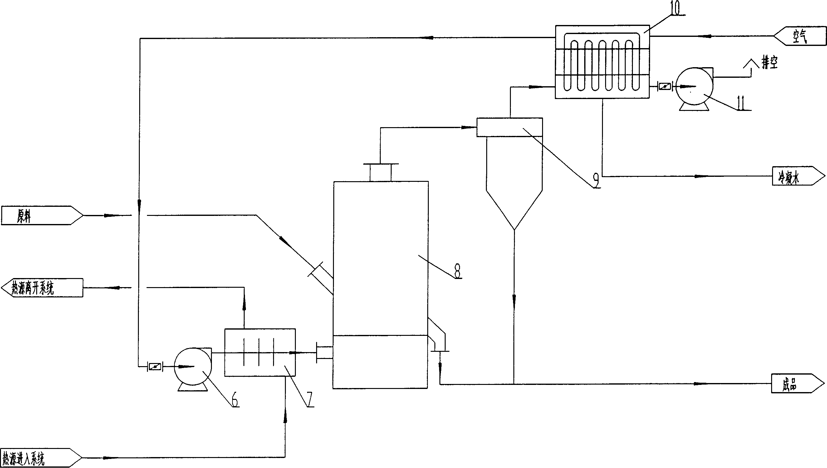
[0029] figure 1 Among them, the oscillating flow heat pipe heat exchanger 10 is a box structure, in which the oscillating flow heat pipe is made of at least one row of Φ1-Φ5mm copper pipes or pipes made of other materials, bent into a serpentine closed loop, and placed vertically. Two adjacent rows of heat pipes are arranged in a staggered manner, making reasonable use of space and increasing the heat exchange area. The vacuum degree in the tube is 1×10 -1 ~1×10 -2 Pa, the working fluid packaged in the tube is pure distilled water or absolute ethanol or acetone or Freon, and the filling rate is 40% to 70%. The heating end 1 of the oscillating flow heat pipe is arranged in the exhaust gas header 2, and the exhaust gas header 2 is located at the bottom of the oscillating flow heat pipe heat exchanger 10; the cooling end 4 of the oscillating flow heat pipe is arranged in the air header 5, and the air header 5 is located in the oscillating flow The top of the heat pipe heat exc...


PUM


Abstract

An energy- saving dry process using air preheater of oscillation stream heat tube includes sending wet material into dryer by conveying device, preheating natural air by said air preheater then using blower to pressurize it and to send it to heat exchanger, heating air to be required temperature and sending it to dryer for drying material in dryer, discharging dried material out from dryer and conveying it together with dried powder collected from cyclone dust remover to final product area, sending tail gas from dryer to said air preheater through draught fan after it is purified by said dust remover and using it to preheat drying media then exhausting it to the air.

Description

technical field [0001] The invention relates to a drying system waste heat recovery technology, in particular to an oscillating flow heat pipe air preheater and an energy-saving drying process using the same. Background technique [0002] At present, in the drying or calcination system, the tail gas temperature is generally higher than 100°C. The moisture contained in the tail gas exists in a gaseous state, part of which comes from the air used for drying, and most of the rest is the moisture removed from the wet material. If it is directly emptied, a large amount of sensible heat and latent heat of water vapor carried in the exhaust gas will be lost, which will cause a great waste of energy. Since the tail gas also contains a certain amount of dust and is in a gaseous state, it is very difficult to recover the waste heat of the dry tail gas. [0003] Usually, in the heat exchanger for waste heat recovery, because the heat transfer coefficient of exhaust gas is low, the he...

Claims


Application Information

Patent Timeline
21 Feb 2007
Publication
CN1916546A
IPC
F28D15/00; F26B23/10
Inventors
董宪华; 郭文