This helps you quickly interpret patents by identifying the three key elements:
Problems solved by technology
Method used
Benefits of technology
Problems solved by technology
[0003] In the existing technology, traditional single-layer thermal storage materials such as rock wool and aluminum silicate fiber are mainly used for pipe insulation. The single-layer structure not only has poor thermal insulation performance, but also has a large heat loss, and such a structure is used for 3-4 years. Afterwards, the thermal insulation effect dropped rapidly, the temperature of the outer surface of the thermal insulation layer gradually increased, and the heat loss was very serious, which not only increased the production cost, but also increased the load of the device, and there would be safety hazards in the long-term operation of the production device under this condition
Method used
Image
Click on the blue label to locate the original text in one second.
Reading with bidirectional positioning of images and text.
Examples
Embodiment 1
[0044] Shougang steelmaking RH furnace superheated steam pipe insulation renovation project, pipe diameter DN325, length 906m, medium temperature 285 ℃, the experimental implementation steps are as follows:
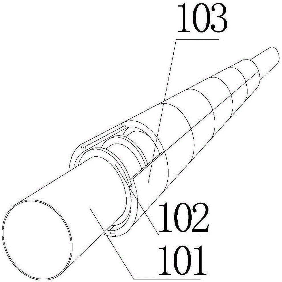
[0045] 1. Install a layer of thermal insulation layer 103 containing fiber material close to the pipeline or equipment substrate 101, and the thickness of the thermal insulation layer 103 is controlled at 12mm;
[0046] 2. A ring-shaped barrier 102 is arranged between the pipeline or equipment base 101 and the insulation layer 103 to form a cavity structure, and the barriers are arranged equidistantly along the surface of the pipeline or equipment base;
[0047] 3. The outer side of the thermal insulation layer 103 is installed with a full normal emissivity. The emission layer of the thermal barrier emission glass is selected, and the thickness is 50mm. According to the surface shape of the thermal equipment and the pipeline, it is cut into a plurality of thermal insulatio...
Embodiment 2
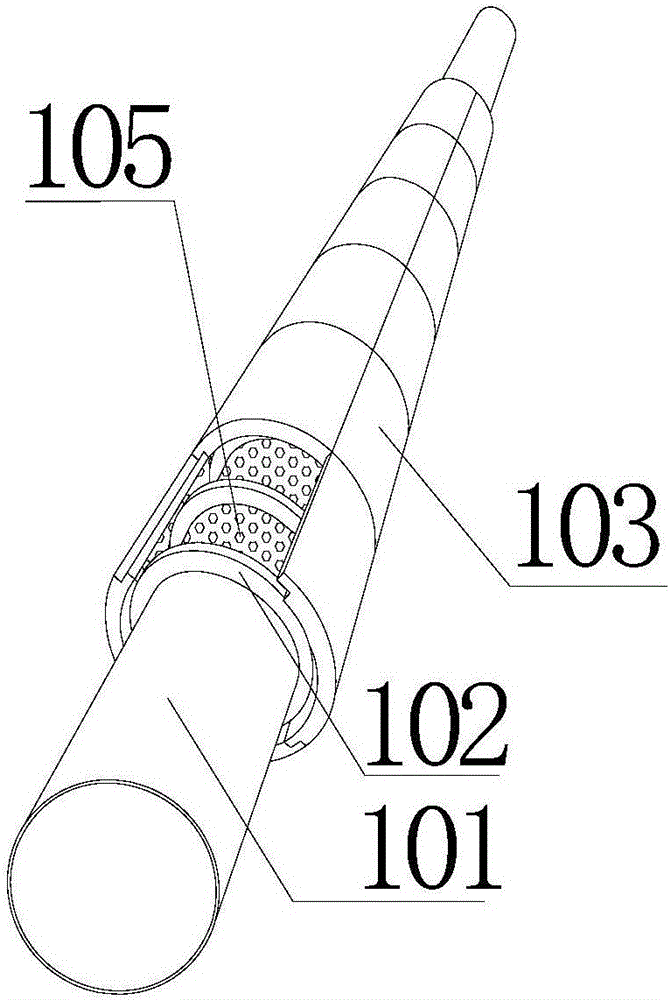
[0054] The other operation steps are basically the same as in Embodiment 1, except that in step 2, the cavity structure is filled with fillers 105, and the fillers 105 are one or more of insulating particles, vacuum materials, and emission materials.
[0055] See attached for specific structure figure 2 , with figure 2 In the middle, only the cavity structure and the connection relationship between the two related layers are highlighted, and other structures such as the emission layer and the inner protection layer are not reflected.
Embodiment 3
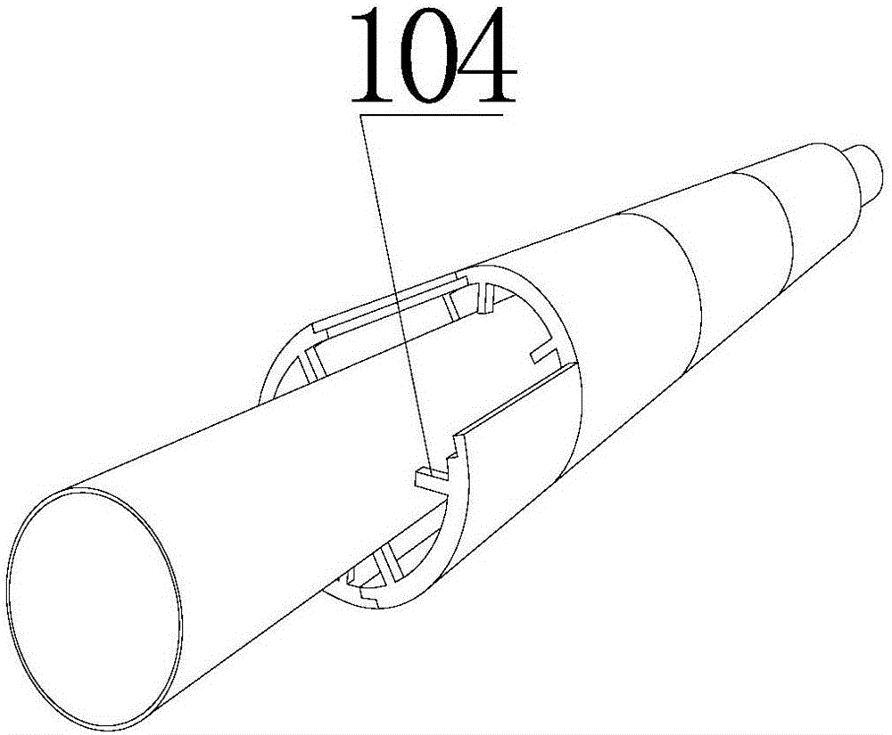
[0057] Other operating steps are basically the same as in Embodiment 1, except that in Step 2, a bracket 104 is provided between the pipeline or equipment base 101 and the insulation layer 103 to form a cavity structure.
[0058] See attached for specific structure image 3 , with image 3 In the middle, only the cavity structure and the connection relationship between the two related layers are highlighted, and other structures such as the emission layer and the inner protection layer are not reflected.
PUM
Abstract
The invention provides a composite insulating layer with cavity structures. The composite insulating layer comprises a pipeline or equipment substrate and at least one insulating layer, wherein block ratings or supports are arranged between the pipeline or equipment substrate and the insulating layer to form part of the cavity structures; block gratings or supports are arranged between the insulating layers to form the rest cavity structures. According to the composite insulating layer with the cavity structures, provided by the embodiment of the invention, as air has a favorable heat insulation effect, equivalently, air layers are added to a common insulating layer structure, and the heat insulation effect of the air layers per se are better than that of the traditional insulating layers, the cost is lowered, heat loss is reduced, successful normal production is guaranteed, the expenditure on frequently replacing the insulating layers is reduced for enterprises, and a certain economical benefit is created.
Description
technical field [0001] The invention relates to the field of heat preservation and cold preservation of high and low temperature pipelines and equipment, in particular to a composite heat preservation layer with a cavity structure. Background technique [0002] Nowadays, due to the large number of pipelines on the production equipment of power plants, chemical plants and many production enterprises, taking good insulation measures for pipelines not only has the practical significance of saving energy and reducing consumption, but also can reduce production costs from the source, so as to achieve energy saving and reduction. row purpose. When selecting pipeline insulation materials, in addition to considering the thermal conductivity of the material, the water absorption rate, combustion performance, strength and other indicators of the material should also be considered. [0003] In the existing technology, traditional single-layer thermal storage materials such as rock woo...
Claims
Application Information
Patent Timeline
Application Date:The date an application was filed.
Publication Date:The date a patent or application was officially published.
First Publication Date:The earliest publication date of a patent with the same application number.
Issue Date:Publication date of the patent grant document.
PCT Entry Date:The Entry date of PCT National Phase.
Estimated Expiry Date:The statutory expiry date of a patent right according to the Patent Law, and it is the longest term of protection that the patent right can achieve without the termination of the patent right due to other reasons(Term extension factor has been taken into account ).
Invalid Date:Actual expiry date is based on effective date or publication date of legal transaction data of invalid patent.