

Differential signal cable
A differential signal and cable technology, which is applied in the field of high-speed data transmission, can solve the problems that the relative dielectric constant cannot be effectively reduced, the effective relative dielectric constant cannot be reduced, and the cable volume can be reduced, so as to reduce the effective relative dielectric constant. Electric constant, relative permittivity is small, and the effect of reducing the size of the cable
- Summary
- Abstract
- Description
- Claims
- Application Information
AI Technical Summary
Problems solved by technology
Method used
Image

Examples
Embodiment 1
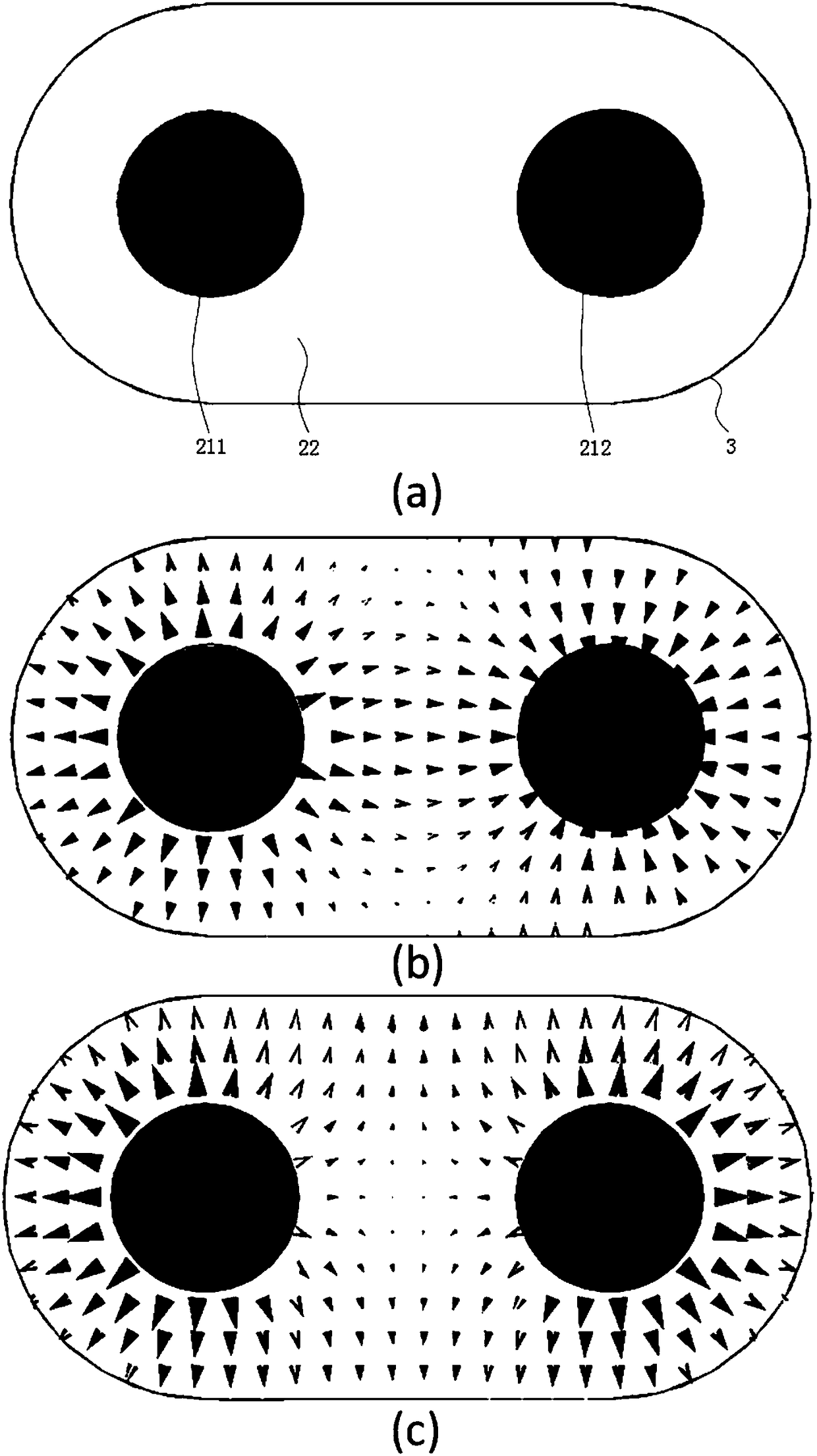
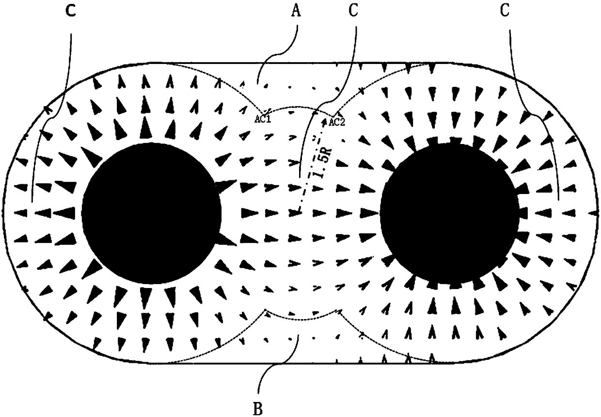
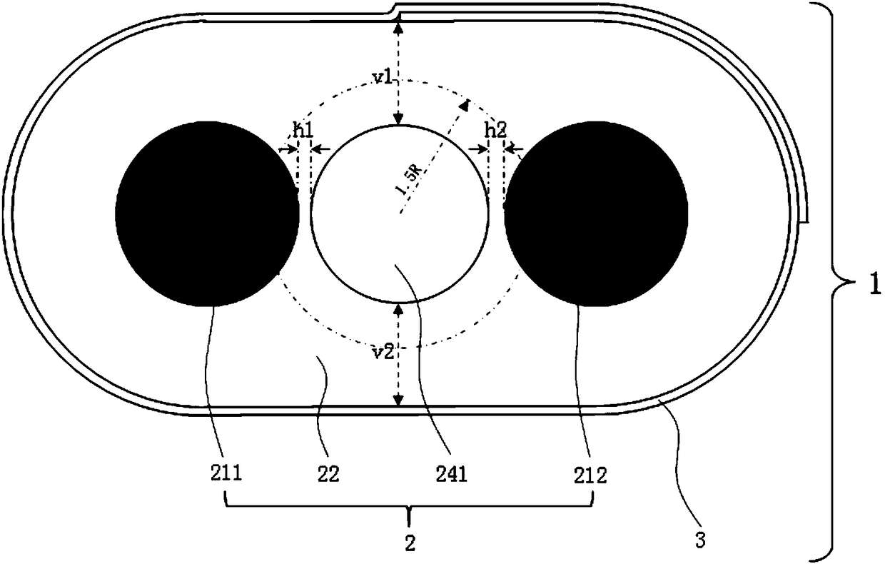
[0064] image 3 It shows the cross-sectional structure diagram of Embodiment 1 of the differential signal cable of the present invention (the view perpendicular to the length direction of the conductor). Depend on image 3 It can be seen that the differential signal cable 1 of the present invention includes an insulated core wire 2 and a shielding layer 3 . The insulated core wire 2 is composed of double conductors 211 , 212 , an insulating medium 22 covering the double conductors 211 , 212 , and a gas gap 241 embedded in the middle of the insulating medium 22 . The gas gap 241 in the middle part is parallel to the double conductors 211, 212, and the center of gravity of the gas gap 241 in the middle part is at the midpoint of the line connecting the centers of the double conductors 211, 212 (the gas gap 241 in the middle part is at the center of the double conductors 211, 212 The line formed by the midpoint of the center line is the central axis, and the radius of 1.5*R is ...
Embodiment 2
[0072] Figure 4 It shows the cross-sectional structural schematic view of Embodiment 2 of the differential signal cable of the present invention (the view perpendicular to the length direction of the conductor). Depend on Figure 4 It can be seen that the differential signal cable 1A of the present invention includes an insulated core wire 2 , a shielding layer 3 and a drain wire 4 . The insulated core wire 2 is composed of double conductors 211 , 212 , an insulating medium 22 covering the double conductors 211 , 212 , and a gas gap 241 embedded in the middle of the insulating medium 22 . The gas gap 241 in the middle part is parallel to the double conductors 211, 212, and the center of gravity of the gas gap 241 in the middle part is at the midpoint of the line connecting the centers of the double conductors 211, 212 (the gas gap 241 in the middle part is at the center of the double conductors 211, 212 The line formed by the midpoint of the center line is the central axis,...
Embodiment 3
[0078] Figure 5 It shows the cross-sectional structure diagram of Embodiment 3 of the differential signal cable of the present invention (the view perpendicular to the length direction of the conductor). Depend on Figure 5 It can be seen that the differential signal cable 1B of the present invention includes an insulating core wire 2 , a shielding layer 3 , drain wires 41 and 42 , and a first stabilizing layer 5 . The insulated core wire 2 is composed of double conductors 211, 212, an insulating medium 22 covering the double conductors 211, 212, an intermediate gas gap 241 embedded in the middle of the insulating medium 22, and a central connection line along the double conductors 211, 212. The mid-vertical plane symmetric gas voids 242 and 243 are embedded symmetrically in the mid-vertical plane. The center of gravity of the gas gap 241 in the middle is at the midpoint of the line connecting the centers of the double conductors 211 and 212 , and the vertically symmetrical...
PUM
| Property | Measurement | Unit |
|---|---|---|
| Density | aaaaa | aaaaa |
Abstract
Description
Claims
Application Information