Flat panel detector communication system and method based on optical fiber interconnection

A technology of flat-panel detector and communication system, which is applied in the direction of TV system, optical fiber transmission, image communication, etc., which is suitable for optical transmission. Effects of cost, reduced power consumption, and thermal stress

Inactive Publication Date: 2018-05-29
SHANGHAI IRAY TECH
View PDF4 Cites 3 Cited by
  • Summary
  • Abstract
  • Description
  • Claims
  • Application Information

AI Technical Summary

Problems solved by technology

[0007] In view of the above-mentioned shortcomings of the prior art, the purpose of the present invention is to provide a flat panel detector communication system and method based on optical fiber interconnection, which is used to solve the problems of short transmission distance, high cost, and high design requirements in the prior art.

Method used


Image

  • Flat panel detector communication system and method based on optical fiber interconnection
  • Flat panel detector communication system and method based on optical fiber interconnection
  • Flat panel detector communication system and method based on optical fiber interconnection

Examples


Embodiment 1

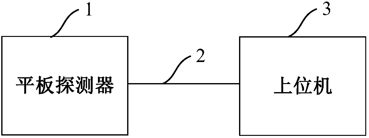
[0056] Such as Figure 1 ~ Figure 3 As shown, this embodiment provides a flat panel detector communication system based on optical fiber interconnection, and the flat panel detector communication system based on optical fiber interconnection includes:

[0057] Flat panel detector 1, optical fiber 2 and host computer 3.

[0058] Such as figure 1 As shown, the output end of the flat panel detector 1 is connected to one end of the optical fiber 2 for image acquisition.

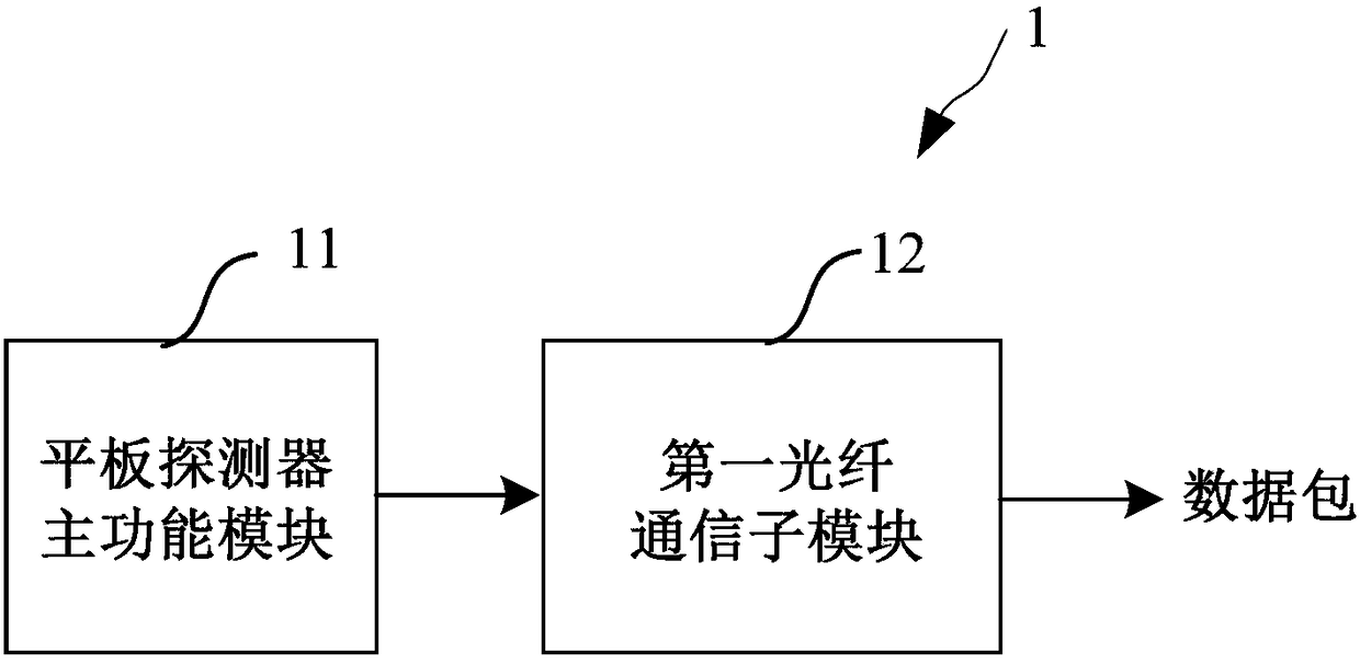
[0059] Specifically, such as figure 2 As shown, the flat panel detector 1 includes a flat panel detector main function module 11 and a first optical fiber communication sub-module 12 .

[0060] More specifically, the flat panel detector main function module 11 is used to collect image information. In this embodiment, the main function module 11 of the flat panel detector includes but not limited to an image detection unit and a control drive unit, and any unit that assists in image detection is applicable to...

Embodiment 2

[0070] This embodiment provides a flat panel detector communication system based on optical fiber interconnection. The difference from Embodiment 1 is that the host computer 3 further includes an image processing module 314 .

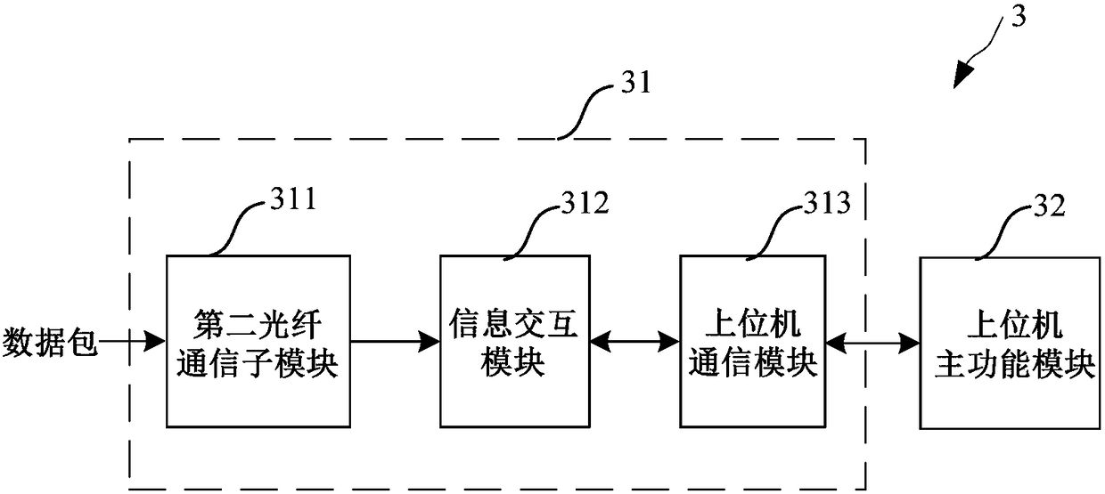
[0071] Specifically, such as Figure 4 As shown, the upper computer 3 includes a second optical fiber communication sub-module 311 , an image processing module 314 , an information interaction module 312 , an upper computer communication module 313 and an upper computer main function module 32 .

[0072] More specifically, the image processing module 314 is connected to the output end of the second optical fiber communication sub-module 311 to process the unpacked image information. The image processing module 314 includes but not limited to an image correction unit and an image preprocessing unit. The image correction unit is used to restore the distorted image; the image preprocessing unit is used to eliminate irrelevant information in the image, res...

Embodiment 3

[0077] This embodiment provides a flat panel detector communication method based on optical fiber interconnection, which is implemented based on the optical fiber interconnection based flat panel detector communication system in Embodiment 1. The optical fiber interconnection based flat panel detector communication method at least includes:

[0078] The flat panel detector collects image information, packs the image information into a data packet, and outputs it through an optical fiber.

[0079] Specifically, such as Figure 1 ~ Figure 2 As shown, the main function module 11 of the flat panel detector collects image information and transmits it to the first optical fiber communication submodule 12, and the first optical fiber communication submodule 12 bases the image information on the flat panel detector The private protocol inside 1 is encoded and encapsulated to obtain a data packet, and transmitted through the optical fiber 2. In practical applications, the data packet ...


PUM


Abstract

The invention provides a flat panel detector communication system and method based on optical fiber interconnection. The system comprises a flat panel detector that is used for collecting images and sending image information based on a first optical fiber communication sub-module, an optical fiber for transmitting the information, and an upper computer that is used for receiving the information based on a second optical fiber communication sub-module, implementing information interaction based on an information interaction module and an upper computer communication module, and identifying anddisplaying the images based on an upper computer main function module. The method includes the following steps: collecting the image information, packing the image information into a data packet, andthen outputting the data packet through the optical fiber; and receiving the data packet through the optical fiber, unpacking the data packet, and then displaying the unpacked image information afteridentification. According to an optical fiber transmission medium adopted by the invention, the transmission bandwidth and reliability can be effectively improved, and the electromagnetic interferenceto other equipment can also be reduced; different rates can be flexibly adopted, and the design difficulty and cost of peripheral hardware equipment can be reduced; and various function sub-modules can be rearranged according to different application scenes to adapt to the harsh conditions in some application occasions.

Description

technical field [0001] The invention relates to the application field of flat panel detectors, in particular to a flat panel detector communication system and method based on optical fiber interconnection. Background technique [0002] The DR system (Digital Radiography, direct digital X-ray photography system) is composed of an electronic cassette, a scan controller, a system controller, and an image monitor. It converts X-ray photons into electrons and then processes them into digital images for display. DR systems are widely used in fields such as medical treatment and performance testing. [0003] Generally, a flat panel detector (FPD, Flat Panel Display) is responsible for image collection, a host computer is responsible for image display, and data transmission is required between the flat panel detector and the host computer. The existing DR system uses Gigabit Ethernet as the image transmission path and twisted pair as the transmission medium. The transmission rate ...

Claims


Application Information

Patent Timeline
Patent Type & Authority Applications(China)
IPC IPC(8): H04N7/22H04N1/32H04B10/25
CPCH04N1/32272H04N7/22H04B10/2589
Inventor 李兆斐郁凯峰洪鹏飞殷志豪
Owner SHANGHAI IRAY TECH
Why Eureka
Try Eureka