
Vehicle suspension vibration damper with relative velocity self-sensing function

A technology of relative speed and vehicle suspension, applied in the direction of suspension, elastic suspension, vehicle components, etc., can solve the problems of shock absorber not being widely used, fixed air gap size, limitation and so on.

Inactive Publication Date: 2007-10-24
CHONGQING UNIV
View PDF5 Cites 0 Cited by
  • Summary
  • Abstract
  • Description
  • Claims
  • Application Information

AI Technical Summary

Problems solved by technology

When this kind of shock absorber works in the actual environment, its working magnetic circuit is easily affected by electromagnetic interference from the body, road surface and the surroundings of the vehicle, so that the voltage signal representing the relative speed generated by the induction coil at both ends of the induction coil is distorted, resulting in Increased error in relative speed sensing
At the same time, since the dust cover of the shock absorber is set outside the cylinder body, and the air gap between the dust cover cover and the cylinder body is designed as an important part of the working magnetic circuit, only when the size of the air gap remains constant can the The induced voltage signal of the induction coil has a good linear proportional relationship with the relative motion speed between the vehicle body and the axle, but it is difficult to ensure that the size of the air gap is constant during the actual vehicle vibration process, resulting in accurate relative speed measurement decrease in speed and stability
In addition, since the dust cover of the shock absorber is used as a part of the closed working magnetic circuit of the relative speed sensor, it is necessary to use a magnetically conductive metal material, and it cannot be popularized for shock absorbers that use other forms of dust cover such as rubber. application
These deficiencies and limitations make the application of invention patents of Thomas et al. limited to a certain extent.

Method used


Image

  • Vehicle suspension vibration damper with relative velocity self-sensing function
  • Vehicle suspension vibration damper with relative velocity self-sensing function
  • Vehicle suspension vibration damper with relative velocity self-sensing function

Examples


Embodiment Construction

[0019] The concrete structure of the present invention is described in detail below in conjunction with accompanying drawing:

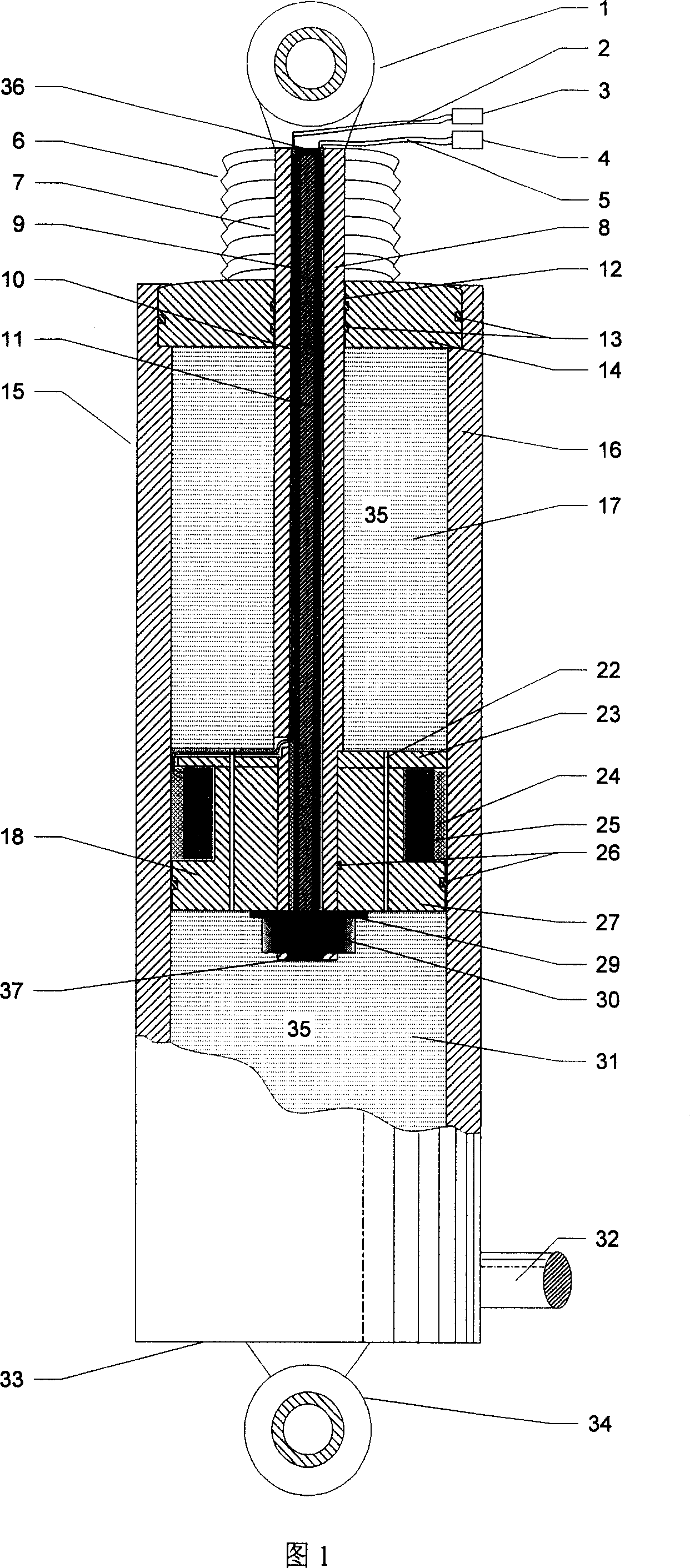
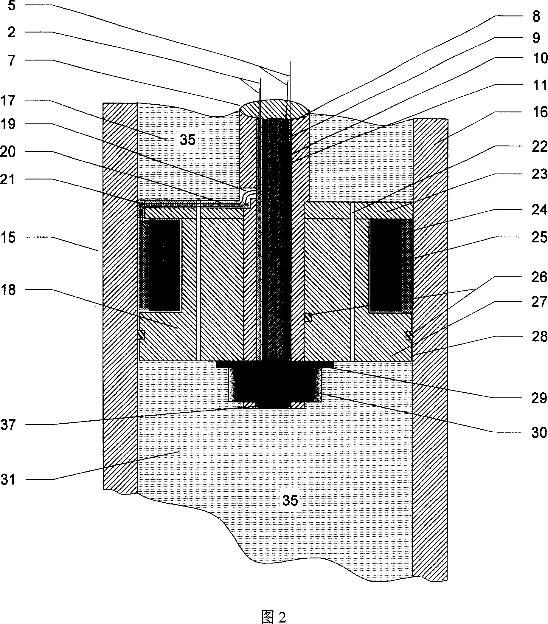
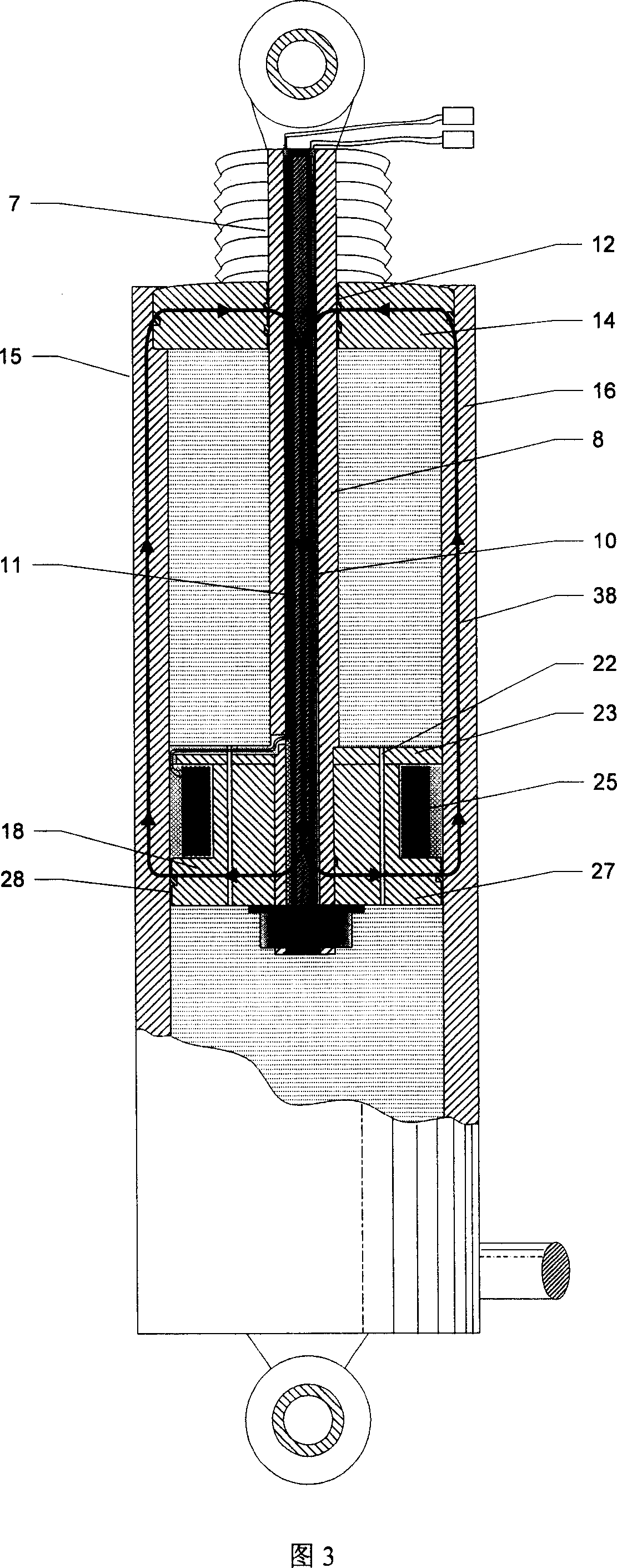
[0020]With reference to Fig. 1, Fig. 2, this vehicle suspension shock absorber mainly comprises cylinder body 15 and the liquid 35 that is contained in cylinder body, piston rod 7, piston head 18, dustproof cover 6, excitation coil 25 on the piston, piston Parts such as the induction coil 10 in the rod. The cylinder body of the shock absorber is mainly composed of a cylinder barrel 16 with high magnetic permeability, an upper end cover 14 and a lower end cover 33 with extremely low magnetic permeability. The lower end cover 33 is provided with a connecting device 34 for connecting the vehicle body or the axle. The piston rod 7 of the shock absorber is formed by processing a low magnetic permeability material, and the outer end of the piston rod is provided with a ring connection device 1 for connecting the vehicle body or the axle. The piston rod 7 i...


PUM


Abstract

The invention relates to a kind of automobile suspension shock absorber with self sensing function of relative speed . It consists of cylinder block and the liquid in it , dust cap , piston head , piston rod , the magnet exciting coil on the piston head , the induction coil in the piston rod , etc . When load alternating voltage signal in middle frequency to the magnet exciting coil , it will produce same-frequency alternating magnetic field which will form a closed magnetic circuit in the shock absorber and make the induction coil produce a alternating voltage signal in the same frequency . The shock of the automobile will induce the corresponding linear change to the magnetic linkage of induction coil , the voltage signal produced in the two end of the coil will be a double sidebands amplitude-modulated signal among which the range adjusting signal reflects relative speed between automobile body and automobile bridge , thus realize the sensing of the relative speed between the automobile body and automobile bridge , thus make the shock absorber not only get the damping function but also get the self sensing function of relative speed , and further realize the self-adapting damp shock reducing of the automobile suspension system .

Description

technical field [0001] The invention relates to a vehicle suspension shock absorber, in particular to a shock absorber with a relative speed self-sensing function designed for a semi-active vehicle suspension system with controllable damping force. technical background [0002] Vehicle suspension refers to the general term for all force transmission connection devices between the body and the axle. The suspension system of the vehicle directly determines the ride comfort and handling stability of the vehicle. In recent years, in order to improve the performance of the suspension system, improve the ride comfort and handling stability of the vehicle, people have researched and developed a variety of semi-active suspension systems. The semi-active vehicle suspension system with controllable damping force is mainly composed of sensors, shock absorbers, springs, electronic control devices, electronically controlled servo valves, accumulators (including liquid storage tanks and ...

Claims


Application Information

Patent Timeline
Patent Type & Authority Patents(China)
IPC IPC(8): B60G17/00
Inventor 王代华赖大坤
Owner CHONGQING UNIV
Learn More