Method of manufacturing micro thermoelectric device through cutting and bonding
A thermoelectric device and micro technology, which is applied in the manufacture/processing of thermoelectric devices, can solve problems such as difficulties in mechanical processing and array arrangement, and achieve the effects of solving difficulties in mechanical processing and array arrangement, low cost and simple preparation process
- Summary
- Abstract
- Description
- Claims
- Application Information
AI Technical Summary
Problems solved by technology
Method used
Image
Examples
preparation example Construction
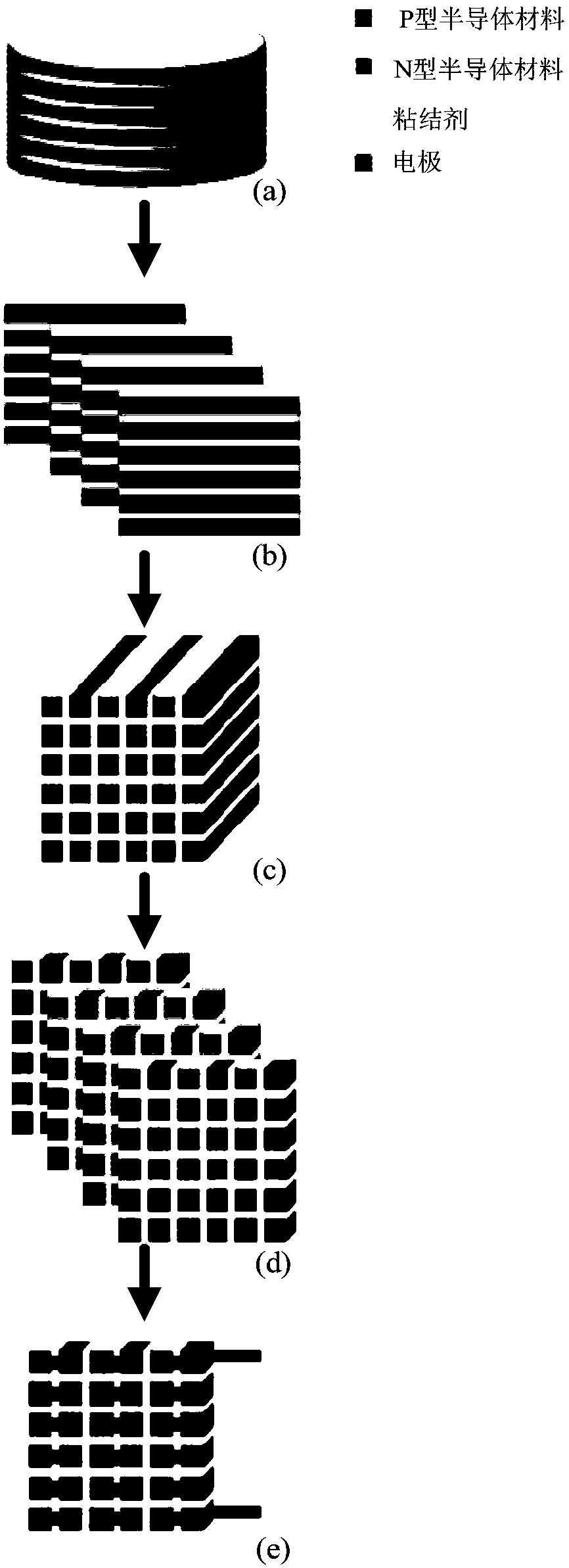
[0021] figure 1 Shown is the process flow chart of the method for preparing micro-thermoelectric devices provided by the embodiment, see figure 1 , the method includes the following steps:
[0022] (1) After cutting the P-type and N-type bulk thermoelectric materials into thin sheets with a diamond wire cutting machine, the P-type and N-type thin sheets are alternately bonded in the order of P-N-P-N with an adhesive, and the thin-sheet composite column is obtained after curing Body, such as figure 1 as shown in (a);
[0023] (2) Cut the thin-sheet composite cylinder along a direction perpendicular to the bottom surface of the thin-sheet composite cylinder to obtain a composite sheet, such as figure 1 As shown in (b), epoxy resin is used to bond the composite sheets according to the alternating pattern of P-type thermoelectric materials and N-type thermoelectric materials, and after curing, a thermoelectric arm array column is obtained, as shown in figure 1 As shown in (c),...
Embodiment 1
[0027] In this embodiment, the epoxy value of the epoxy resin is 0.5-0.55 / 100g, and the addition amount of glass microspheres is 5%, and the particle size range is 60-90 μm. The measured thermal conductivity was 0.05662 W / mK.
[0028] The process of preparing micro thermoelectric devices is as follows:
[0029] (1) Use a diamond wire cutting machine to cut out 3 thin slices each with a thickness of 700 μm from the P-type and N-type bulk thermoelectric materials, and alternately bond them with epoxy resin, and obtain thin slice composite columns after curing;
[0030] (2) Cut the composite columnar vertical bottom surface of the flakes obtained in step (1) again to obtain 6 composite flakes with a thickness of 700 μm, reverse 3 of them, and alternately bond them with the other 3 flakes, and obtain a thermoelectric arm array column after curing body.
[0031] (3) Carry out the third cut vertically to the bottom surface of the cylinder to obtain the thermoelectric arm array;
...
Embodiment 2
[0034] In this embodiment, the epoxy value of the epoxy resin is 0.5-0.55 / 100g, and the addition amount of glass microspheres is 13%, and the particle size range is 25-30 μm. The measured thermal conductivity was 0.05012 W / mK.
[0035] The process of preparing micro thermoelectric devices is as follows:
[0036] (1) Use a diamond wire cutting machine to cut out 3 thin slices each with a thickness of 700 μm from the P-type and N-type bulk thermoelectric materials, and alternately bond them with epoxy resin, and obtain thin slice composite columns after curing;
[0037] (2) Cut the composite columnar vertical bottom surface of the flakes obtained in step (1) again to obtain 6 composite flakes with a thickness of 700 μm, reverse 3 of them, and alternately bond them with the other 3 flakes, and obtain a thermoelectric arm array column after curing body.
[0038] (3) Carry out the third cut vertically to the bottom surface of the cylinder to obtain the thermoelectric arm array; ...
PUM
| Property | Measurement | Unit |
|---|---|---|
| Particle size | aaaaa | aaaaa |
| Particle size | aaaaa | aaaaa |
| Particle size | aaaaa | aaaaa |
Abstract
Description
Claims
Application Information
 - R&D Engineer
- R&D Manager
- IP Professional
- Industry Leading Data Capabilities
- Powerful AI technology
- Patent DNA Extraction
Browse by: Latest US Patents, China's latest patents, Technical Efficacy Thesaurus, Application Domain, Technology Topic, Popular Technical Reports.
© 2024 PatSnap. All rights reserved.Legal|Privacy policy|Modern Slavery Act Transparency Statement|Sitemap|About US| Contact US: help@patsnap.com


