Millimeter-wave high-gain circularly polarized horn antenna loaded with a single dielectric plane lens

A technology of planar lens and horn antenna, which is applied in the direction of waveguide horn, antenna, electrical components, etc., can solve the problems of multi-layer unit thickness and weight, high processing difficulty, large volume, etc., and achieve light weight, low cost, and compact volume Effect

Active Publication Date: 2020-12-22
SHANGHAI RADIO EQUIP RES INST
View PDF6 Cites 1 Cited by
  • Summary
  • Abstract
  • Description
  • Claims
  • Application Information

AI Technical Summary

Problems solved by technology

The three-dimensional electromagnetic lens mainly uses the curved surface shape of the dielectric material to realize the function of electromagnetic wave phase compensation. The curved surface medium has continuous phase compensation characteristics, small phase error, and wide frequency bandwidth, but there are still problems such as relatively large volume and high processing difficulty.
The resonant periodic unit often has the characteristics of narrow band, and the multi-layer unit has a wider bandwidth but there are problems with thickness and weight

Method used


Image

  • Millimeter-wave high-gain circularly polarized horn antenna loaded with a single dielectric plane lens
  • Millimeter-wave high-gain circularly polarized horn antenna loaded with a single dielectric plane lens
  • Millimeter-wave high-gain circularly polarized horn antenna loaded with a single dielectric plane lens

Examples


Embodiment Construction

[0031] The following combination Figure 1 to Figure 9 , the technical content, structural features, achieved goals and effects of the present invention will be described in detail through preferred embodiments.

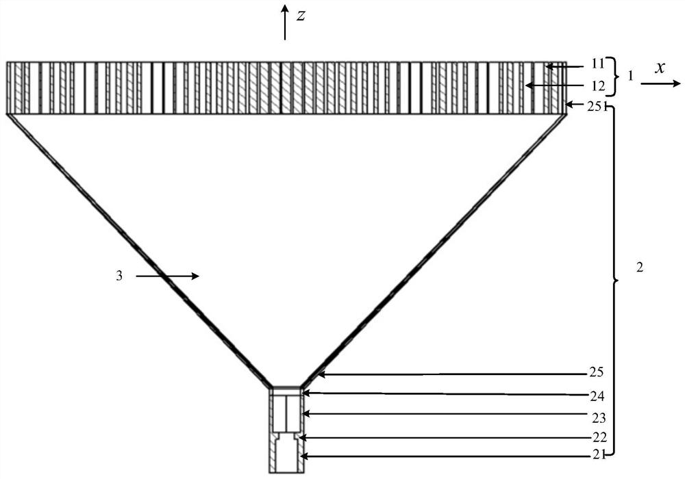
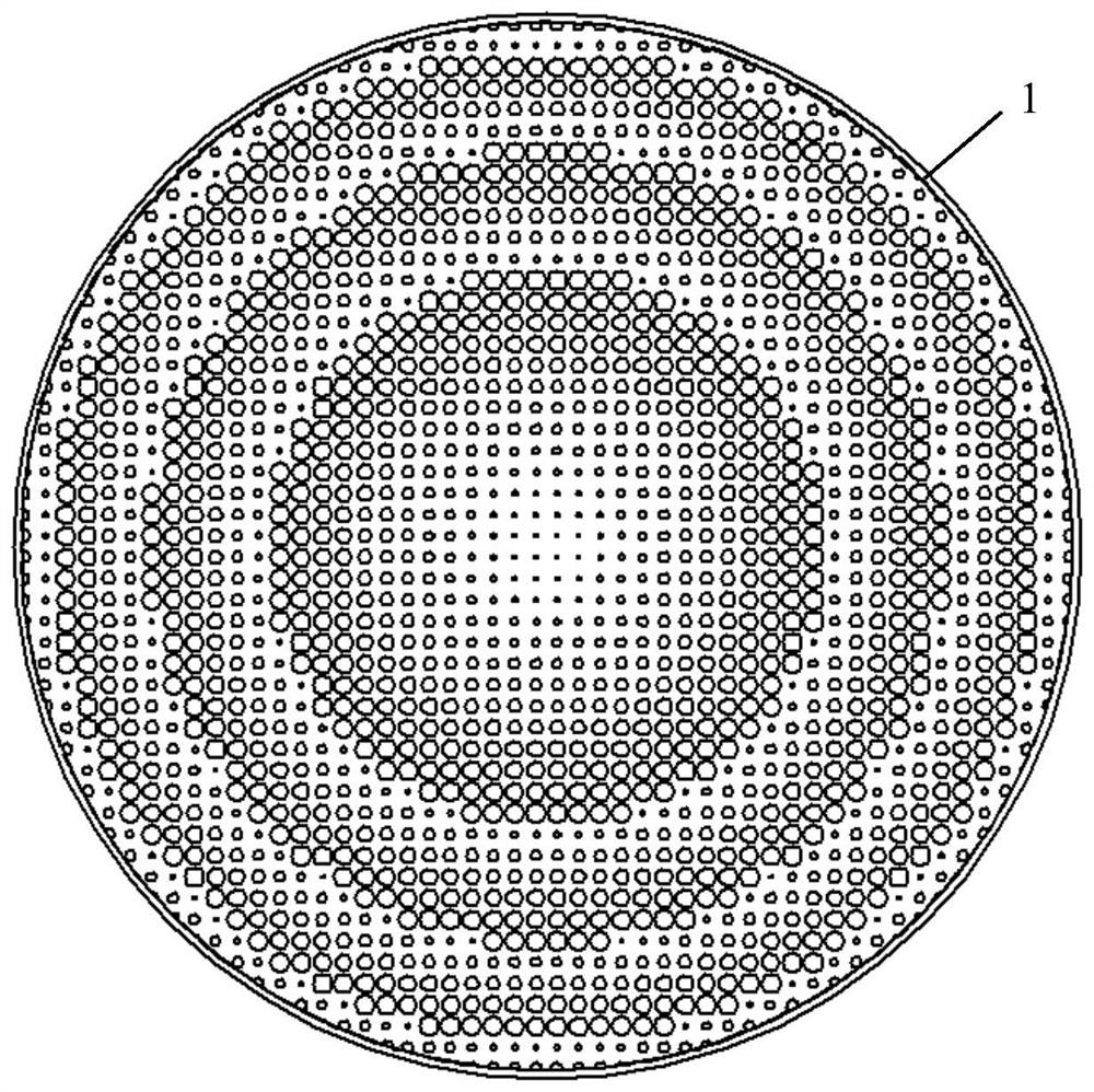
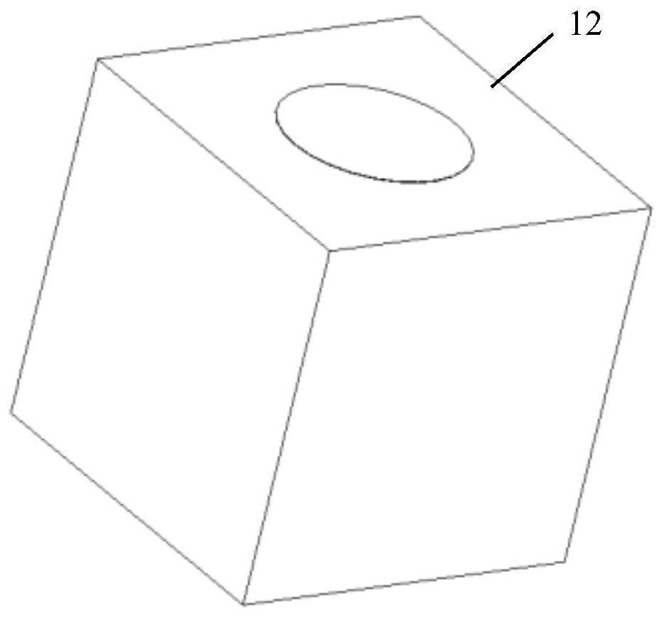
[0032] Such as figure 1 As shown, the millimeter-wave high-gain circularly polarized horn antenna provided by the present invention is loaded with a single dielectric plane lens, which is a layered structure, including a circularly polarized horn antenna body 2, and covering the circularly polarized horn antenna body. 2 a single-dielectric plane lens 1 above the top; wherein, the single-dielectric plane lens 1 includes a dielectric substrate 11, and a plurality of array units 12 embedded in the dielectric substrate 11; the circularly polarized horn The antenna main body 2 includes a rectangular waveguide 21, a rectangular waveguide transition section 22, a circular waveguide 23 with a chamfered angle, a circular waveguide transition section 24, and a horn-shaped cir...


PUM


Abstract

The invention relates to a millimeter-wave high-gain circular polarization horn antenna with a loaded single-medium planar lens. The millimeter-wave high-gain circular polarization horn antenna comprises a circular polarization horn antenna body and a single-medium planar lens which is arranged above the top of the circular polarization horn antenna body for covering, wherein the single-medium planar lens comprises a medium substrate and a plurality of array units which are embedded into the medium substrate. The array unit has a structure form in which a circular through hole exists at the center of a square cylinder. Furthermore in the medium substrate, arrangement is performed according to a phase compensation principle algorithm based on a feed source phase center. The circular polarization horn antenna body comprises a rectangular waveguide, a circular waveguide with a chamfering angle, and a horn-shaped circular open waveguide, wherein the rectangular waveguide, the circular waveguide and the horn-shaped circular open waveguide are successively arranged from bottom to top. According to the millimeter-wave high-gain circular polarization horn antenna, the array unit with the circular through hole is used as a basic unit of the single-medium planar antenna; through adjusting the diameter of the circular through hole of each array unit, phase distribution is controlled and aphase compensation function on the electromagnetic wave which is transmitted from the circular polarization horn antenna is realized; and a purpose of improving gain and directionality is realized.

Description

technical field [0001] The invention relates to an antenna, specifically a high-gain, wide-band, integrated millimeter-wave circularly polarized horn antenna loaded by a single-dielectric plane lens, which belongs to the technical field of antenna design and is mainly used in satellite communication, radar, imaging, etc. field. Background technique [0002] In recent years, with the vigorous development of modern communication and radar technology, the spectrum resources of the traditional low microwave frequency band have become increasingly tight. Therefore, the millimeter wave band, with its rich spectrum resources, has increasingly become a hot issue for researchers to explore and pay attention to. Due to its compact structure, millimeter-wave antennas can obtain high gain, directivity and narrow beamwidth, and have important application prospects in radar, imaging, satellite communication and other fields. [0003] The horn antenna is a commonly used power radiator, wh...

Claims


Application Information

Patent Timeline
Patent Type & Authority Patents(China)
IPC IPC(8): H01Q19/06H01Q13/02H01Q15/02
CPCH01Q13/0241H01Q15/02H01Q19/06
Inventor 江梅鲁洵洵商远波黄勇玄晓波
Owner SHANGHAI RADIO EQUIP RES INST
Why Eureka
Try Eureka