Hybrid, symmetrical and active boost network converter

A network conversion and symmetry technology, applied in the direction of conversion equipment without intermediate conversion to AC, can solve the problems of large voltage stress of switching tube and output diode, weak boosting capability, low efficiency, etc., to improve the boosting capability, increase Boosting capability, the effect of improving the vertical boosting capability

Inactive Publication Date: 2018-06-01
SOUTHEAST UNIV
View PDF2 Cites 5 Cited by
  • Summary
  • Abstract
  • Description
  • Claims
  • Application Information

AI Technical Summary

Problems solved by technology

[0003] Purpose of the invention: The purpose of the invention is to provide a hybrid symmetric active boost network converter that can solve the problems of weak boosting capability, low efficiency, and large voltage stress of the switch tube and output diode of the traditional converter

Method used


Image

  • Hybrid, symmetrical and active boost network converter
  • Hybrid, symmetrical and active boost network converter
  • Hybrid, symmetrical and active boost network converter

Examples


Embodiment Construction

[0026] The technical solution of the present invention will be further introduced below in combination with specific implementation methods and accompanying drawings.

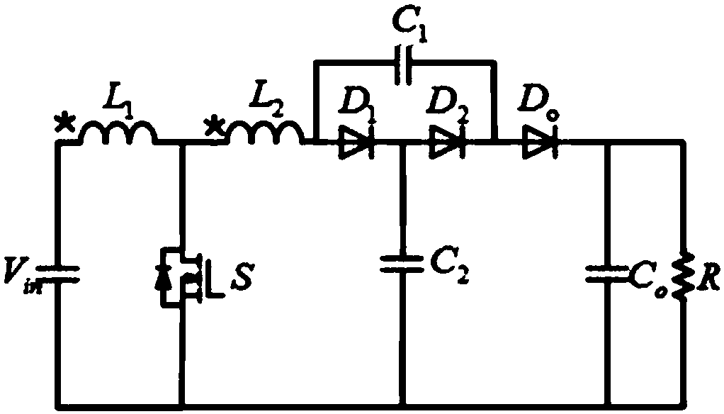
[0027] The first specific embodiment discloses a hybrid symmetrical active boost network converter, such as figure 1 shown, including the input supply V in , input supply V in The positive pole of the coupled inductor is connected to the primary winding L 1 The terminal of the same name, the primary winding L of the coupled inductor 1 The opposite ends of the coupled inductors are respectively connected to the secondary winding L of the coupled inductor 2 The terminal with the same name and the drain of the switch tube S, the secondary winding L of the coupled inductor 2 The opposite ends of the terminals are respectively connected to the capacitor C 1 One end of the rectifier diode D 1 anode of the rectifier diode D 1 The cathodes are respectively connected to the rectifier diode D 2 anode and capacito...


PUM


Abstract

A hybrid, symmetrical and active boost network converter disclosed by the present invention comprises an input power supply Vin, the anode of the input power supply Vin is connected with a same name end of a coupling inductor primary winding L1, and the different name end of the coupling inductor primary winding L1 is connected with the same name end of a coupling inductor secondary winding L2 andthe drain of a switching tube S separately. The different name end of the coupling inductor secondary winding L2 is connected with one end of a capacitor C1 and the anode of a rectifier diode D1 separately, the cathode of the rectifier diode D1 is connected with the anode of a rectifier diode D2 and one end of a capacitor C2 separately, and the cathode of the rectifier diode D2 is connected withthe other end of the capacitor C1 and the anode of a rectifier diode D0 separately. The cathode of the rectifier diode D0 is connected with one end of an output capacitor C0 and one end of a load resistor R separately, and the other end of the output capacitor C0, the other end of the load resistor R, the other end of the capacitor C2 and the source of the switching tube S are connected with the cathode of the input power supply Vin separately. The boost network converter of the present invention effectively solves the problems that the conventional converter is weak in boost capability and low in efficiency, and the switching tube and an output diode are large in voltage stress.

Description

technical field [0001] The invention relates to a boost network converter, in particular to a hybrid symmetrical active boost network converter. Background technique [0002] With the continuous shortage of fossil energy and the aggravation of environmental pollution, the demand for renewable energy has become increasingly prominent. The distributed power generation system based on new energy and renewable energy has become a research hotspot, and the straight-to-straight converter is one of them. component. More and more people in the world look forward to the use and development of renewable energy in daily life. Photovoltaic power generation systems, fuel cell systems, etc. have been widely used in today's production activities. However, due to the influence of family planning parameters of conventional BOOST converters, its duty cycle cannot be too high, so the voltage of BOOST converters The gain capability is low, the voltage stress of the switching tube and output d...

Claims


Application Information

Patent Timeline
Patent Type & Authority Applications(China)
IPC IPC(8): H02M3/07
CPCH02M3/07
Inventor 林明耀艾建孔永杨公德刘同民李晖乐伟
Owner SOUTHEAST UNIV
Why Eureka
Try Eureka