
Heavy ion synchroaccelerator

A synchrotron, heavy ion technology, applied in magnetic resonance accelerators, accelerators, electrical components, etc., can solve the problems of inconvenient magnet processing, high beam current intensity, magnet installation difficulty, etc., to facilitate beam debugging and installation. , The magnetic focusing structure is simple and the layout is optimized.

Active Publication Date: 2018-06-01
惠州离子科学研究中心 +1
View PDF10 Cites 6 Cited by
  • Summary
  • Abstract
  • Description
  • Claims
  • Application Information

AI Technical Summary

Problems solved by technology

Among them, 201210264179.2 is very suitable for proton cancer treatment accelerators. Although it is suitable for heavy ion cancer treatment accelerators, due to the structure of 6 two-pole magnets, a single two-pole magnet weighs 20 tons and has a bending arc of 60 degrees. It is convenient for the processing of the magnet, but also brings difficulty to the installation of the magnet; and the patent 201010252492.5 uses eight 45-degree deflection dipole magnets, and uses a cyclotron as the injector, so it is difficult to achieve a higher beam current intensity. lead to longer treatment times
In addition, due to the large deflection angle of the beam at the point where the beam is drawn out of the electrostatic cutter relative to the central orbit of the synchrotron, the electrostatic cutter is required to provide a higher voltage.
In the prior art, there is also an accelerator with a FODO structure, which uses a multi-turn injection method. The slow lead-out electrostatic cutter and the lead-out magnetic cutting iron are placed at a place where the horizontal beam envelope is close to the average value, and the slow lead-out does not use convex rails. , low utilization of the lateral acceptance of the synchrotron

Method used

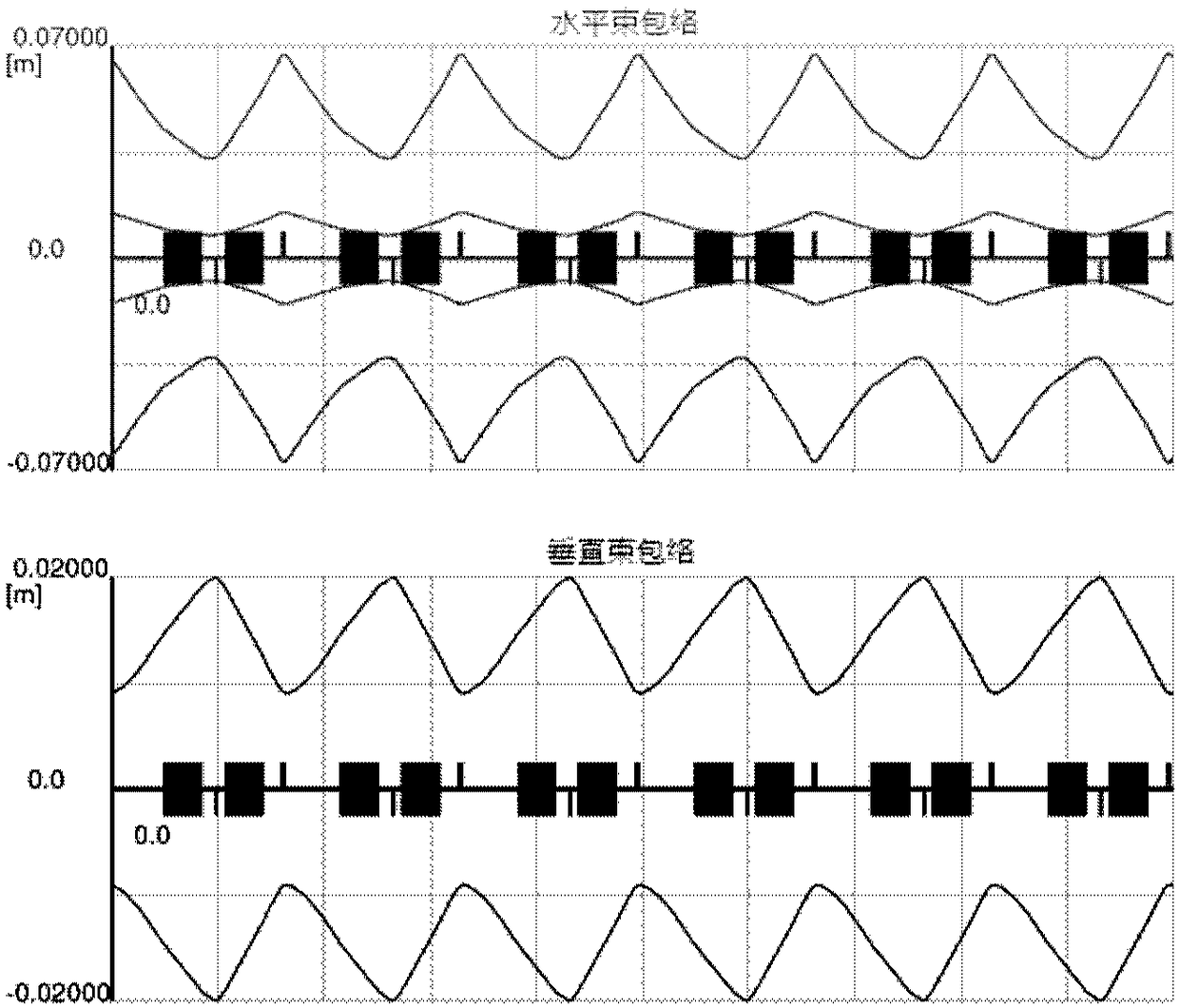
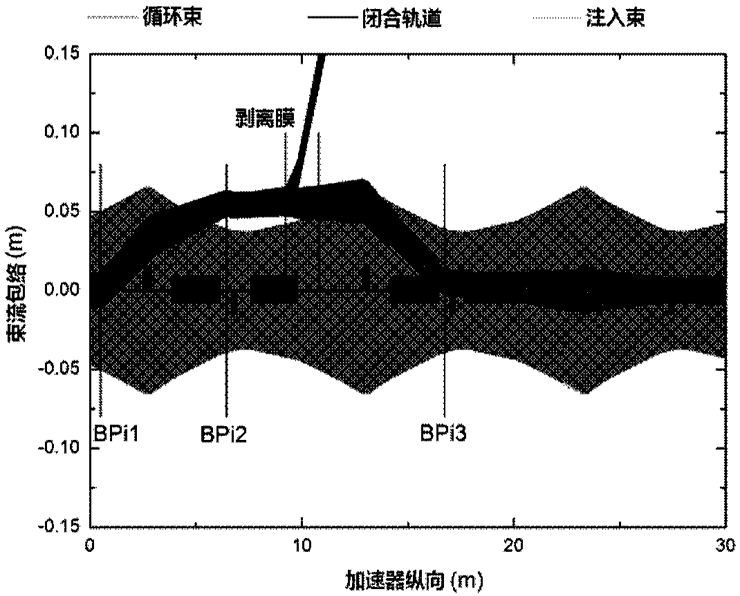

Image

  • Heavy ion synchroaccelerator
  • Heavy ion synchroaccelerator
  • Heavy ion synchroaccelerator

Examples


Embodiment Construction

[0038] In order to make the object, technical solution and advantages of the present invention clearer, the present invention will be further described in detail below in conjunction with specific embodiments and with reference to the accompanying drawings.

[0039] The heavy ion synchrotron of the present invention uses a closed annular vacuum pipeline to provide a high-vacuum environment for beam operation, uses dipole magnets to realize beam deflection, uses quadrupole magnets to realize beam focusing, and uses hexapole magnets to realize chromaticity. Correction and beam resonance, using correction iron for closed-orbit correction.

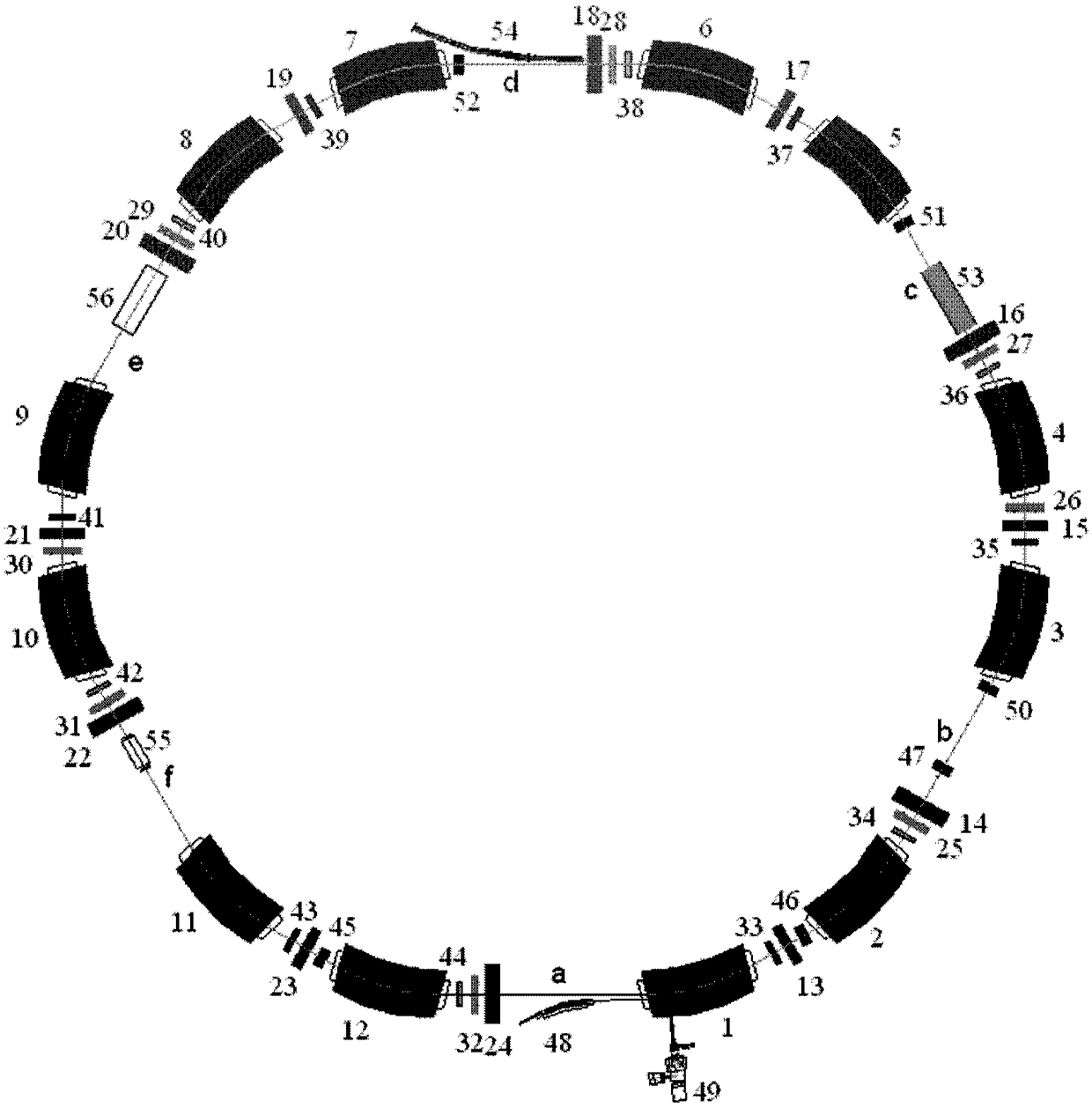
[0040] figure 1 It is the overall layout diagram of the synchrotron. It can be seen from the figure that the synchrotron has a hexagonal structure, and the dipole magnets and quadrupole magnets are arranged very regularly. Starting from the direction of six o'clock and rotating counterclockwise, the components are as follows: injection cuttin...


PUM


Abstract

A heavy ion synchroaccelerator comprises an annular vacuum pipeline, the annular vacuum pipeline has a plurality of linear ion beam sections and a plurality of curve ion beam sections, the linear ionbeam sections and the curve ion beam sections are alternately arranged, heavy ions are injected from a first linear ion beam section and are led out from another linear ion beam section, each curve ion beam section comprises one first dipole magnet and one second dipole magnet which are connected in series, the heavy ions are moved from the first dipole magnets to the second dipole magnets, vertical correcting magnets and vertical focusing quadrupole magnets are arranged in order between the first dipole magnets and the second dipole magnets, the linear ion beam sections at the downstreams ofthe second dipole magnets are provided with horizontal correcting magnets, hexapole magnets and horizontal correcting quadrupole magnets in order. The heavy ion synchroaccelerator is simple in structure, can save processing cost, facilitate installation and debugging of the device, is easier to achieve high accumulation flow intensity, and can fully utilize transverse acceptability of the synchroaccelerator.

Description

technical field [0001] The invention relates to the field of synchrotrons, in particular to a heavy ion synchrotron with a FODO structure. Background technique [0002] Because the irradiation of heavy ion beams on organisms has the characteristics of inverted depth dose distribution, small side scatter, high relative biological effect and low oxygen increase ratio, etc., making heavy ion cancer treatment has become an advanced technology in the world today. Effective radiation therapy for cancer. The beam energy of the commonly used deep heavy ion cancer therapy is 120MeV / u-400MeV / u. [0003] A synchrotron is a device that injects, accelerates, and extracts charged particle beams by controlling the timing structure of the front-end injector, the magnetic field of the synchrotron magnet, the longitudinal high-frequency electric field, the beam diagnosis element, and the injection element. It is widely used in the fields of nuclear physics, nuclear physics, material irradia...

Claims


Application Information

Patent Timeline
IPC IPC(8): H05H13/04
CPCH05H13/04
Inventor 石健夏佳文杨建成
Owner 惠州离子科学研究中心
Learn More