Novel bottom-mounted back pressure heat supply steam turbine and operation method thereof

A steam turbine and bottom-mounted technology, which is applied in the direction of mechanical equipment, steam engine devices, machines/engines, etc., can solve the problems of low efficiency and unreasonable distribution of small steam turbines, achieve low difficulty in transformation, easy popularization, and improve axial safety Effect

Inactive Publication Date: 2018-06-05
SOUTHEAST UNIV
View PDF3 Cites 10 Cited by
  • Summary
  • Abstract
  • Description
  • Claims
  • Application Information

AI Technical Summary

Problems solved by technology

[0007] In order to make up for the deficiencies in the current operation, solve the problems of unreasonable enthalpy drop distribution of traditional bottom-mounted back pressure heating steam turbines, and low efficiency of small steam turbines under variable operating conditions of the main engine load, and maximize the use of the pressure difference energy of steam extraction to improve The efficiency of small steam turbines

Method used


Image

  • Novel bottom-mounted back pressure heat supply steam turbine and operation method thereof
  • Novel bottom-mounted back pressure heat supply steam turbine and operation method thereof
  • Novel bottom-mounted back pressure heat supply steam turbine and operation method thereof

Examples


Embodiment Construction

[0045] The present invention will be further explained below in conjunction with the accompanying drawings and specific embodiments. It should be understood that the following specific embodiments are only used to illustrate the present invention but not to limit the scope of the present invention.

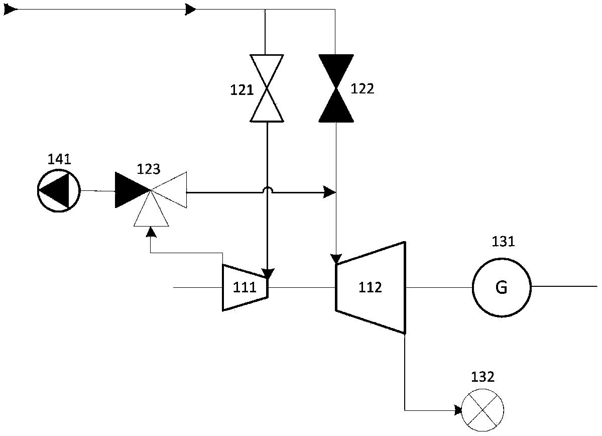
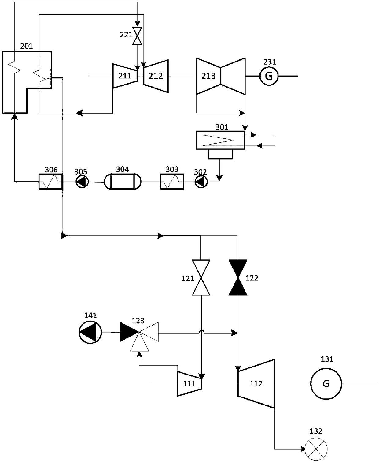
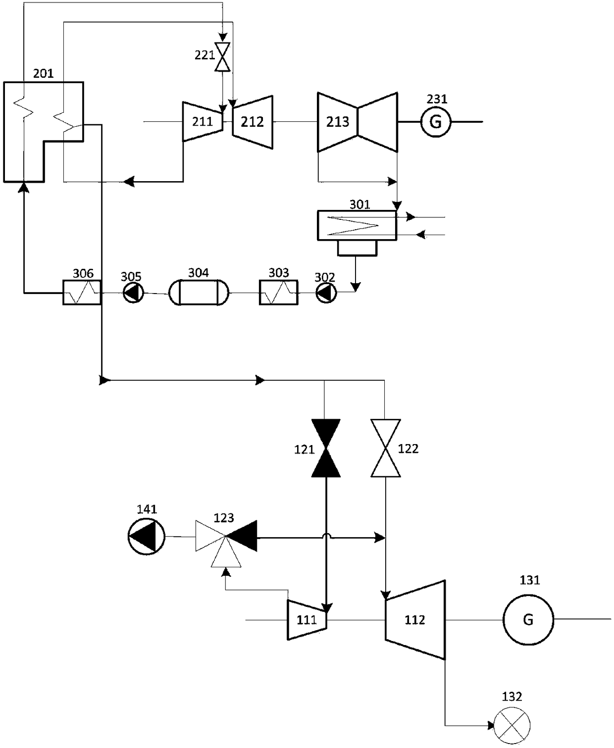
[0046] figure 1 It is a structural diagram of the bottom-mounted backpressure heating steam turbine of the present invention, figure 2 It is a principle diagram of the operation state of the thermal system of the bottom-mounted back-pressure heating steam turbine of the present invention under the high electric load operation condition of the main engine, image 3 It is a schematic diagram of the operation state of the thermal system of the bottom-mounted back-pressure heating steam turbine of the present invention under the low electrical load operating condition of the main engine. The names of the marked components in the figure are: boiler 201, high-pressure cylinder 211 of...


PUM


Abstract

The invention discloses a novel bottom-mounted back pressure heat supply steam turbine and an operation method thereof. The novel bottom-mounted back pressure heat supply steam turbine and the operation method thereof are used in a steam extraction heating heat circulation system of a large pure condensing steam turbine unit. A thermal power plant thermal cycle system includes a boiler and a mainsteam turbine unit. A bottom-mounted back pressure heat supply steam turbine unit comprises a small steam turbine, a steam inlet pipe system and a valve, a high pressure cylinder vacuum pump, a steamexhaust pipe system downstream of a high pressure cylinder, a three-way valve, and a small power frequency generator. The thermal power plant thermal cycle system operates at 40% or more of a grid load command, steam enters the high pressure cylinder of the bottom-mounted back pressure heat supply steam turbine, the high pressure cylinder exhausts steam, a low pressure cylinder continues to expandto do work. The thermal power plant thermal cycle system operates at 40% or less of the grid load command, steam intake of the high pressure cylinder of the bottom-mounted back pressure heat supply steam turbine is stopped, steam enters through the lower pressure cylinder, and the high pressure cylinder vacuum pump of the small steam turbine is started. The novel bottom-mounted back pressure heatsupply steam turbine improves efficiency based on a conventional bottom-mounted back pressure heat supply steam turbine, and the energy utilization rate and comprehensive economy of a heat supply system is maximized as much as possible.

Description

technical field [0001] The invention discloses a novel bottom-mounted back-pressure heat supply steam turbine and an operation method thereof, which are used in a large-scale pure condensing steam turbine unit for extracting steam and supplying heat to a thermodynamic cycle system. Background technique [0002] my country's central heating began in the 1990s and has developed rapidly. [0003] Using large-scale pure condensing turbine units to extract steam and replace surrounding small thermal power units for heat supply can not only improve the thermal energy utilization rate of large thermal power units, but also shut down small units with high energy consumption and high pollution, reduce regional coal consumption, and reduce pollution emissions. This has become an important measure for the whole society to control carbon emissions, and promotes the construction of a resource-saving and environment-friendly society. [0004] For the heating power plants that have realiz...

Claims


Application Information

Patent Timeline
Patent Type & Authority Applications(China)
IPC IPC(8): F01K11/02F01K7/18F01K7/20F01K3/18F01K13/02
CPCF01K11/02F01K3/18F01K7/18F01K7/20F01K13/02
Inventor 杨建明潘杭萍
Owner SOUTHEAST UNIV
Why Eureka
Try Eureka