
Multi-point injection evaporation tube of combustion chamber of micro engine

An evaporating tube and engine technology, which is applied in the combustion chamber, continuous combustion chamber, combustion method, etc., can solve the problems of small contact area, short residence time, poor atomization and evaporation effect, etc., and achieves enhanced heat exchange and atomization fineness. Improve the effect of evenly mixing oil and gas

Inactive Publication Date: 2018-06-08
NORTHWESTERN POLYTECHNICAL UNIV
View PDF6 Cites 1 Cited by
  • Summary
  • Abstract
  • Description
  • Claims
  • Application Information

AI Technical Summary

Problems solved by technology

[0004] The design type of the evaporator tube for fuel supply is mainly the direct injection method, and most of the walls still adopt a smooth wall structure, resulting in a short residence time of the fuel in this type of evaporator tube, a small contact area with the air flow, and a relatively low atomization and evaporation effect. To make the atomization and evaporation effect of the evaporation tube better, the oil supply method and the design of the internal structure play a key role

Method used


Image

  • Multi-point injection evaporation tube of combustion chamber of micro engine
  • Multi-point injection evaporation tube of combustion chamber of micro engine
  • Multi-point injection evaporation tube of combustion chamber of micro engine

Examples


Embodiment Construction

[0018] The present invention will be further described now in conjunction with accompanying drawing:

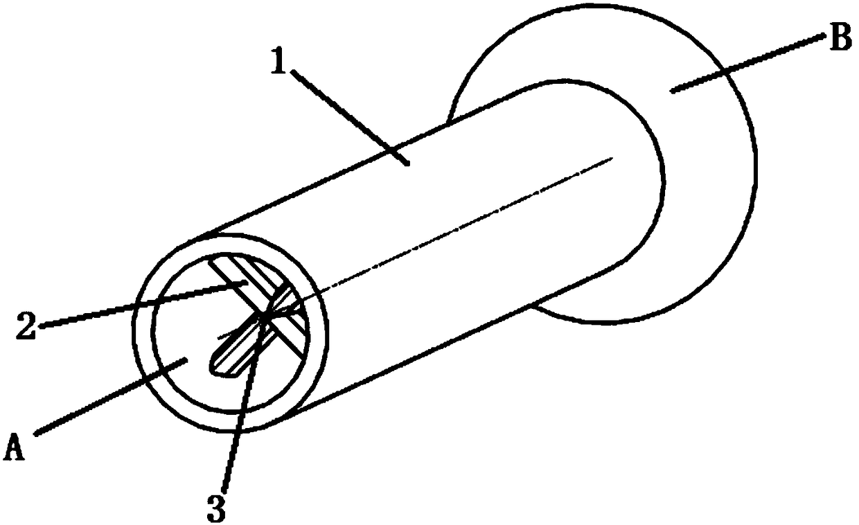
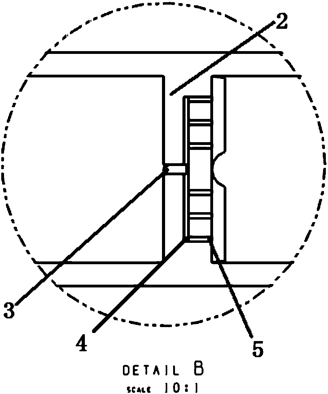
[0019] combine Figure 1 to Figure 3 , the present invention provides a new micro-combustion chamber evaporation tube structure and oil supply mode design that can effectively enhance heat exchange and improve fuel evaporation and atomization. figure 1 It is a three-dimensional diagram of the overall structure of the multi-point jet evaporation tube, which is mainly used to determine the structural shape and geometric distribution of the V-shaped blunt body. figure 2 is a schematic diagram of the central section of the multi-point jet evaporation tube, image 3 It is a partial enlarged view of the layout of the built-in oil circuit of the blunt body of the multi-point jet evaporation tube, which is mainly used to determine the layout of the built-in oil circuit of the blunt body and the position of the oil inlet and outlet holes.

[0020] according to figure 2 As shown, ...


PUM


Abstract

The invention provides a multi-point injection evaporation tube of a combustion chamber of a micro engine. The evaporation tube comprises a V-shaped blunt body structure and a multi-point injection oil path layout mode. The fuel multi-point injection design is used, the atomization fineness of fuel is improved, the contact area of the fuel and air flow is increased, the fuel can be easily crushedand atomized, and the fuel and air are more uniformly mixed. The V-shaped blunt body structure is reasonably designed in the evaporation tube and is internally provided with a fuel multi-point injection oil path, after the air flow passes through the V-shaped blunt body structure, a low-speed stable backflow area is formed, and the fuel is sprayed into the backflow area from branch fuel outlets, so that the stay time of the fuel in the evaporation tube is prolonged, the atomizing and evaporation time becomes longer, meanwhile, the contact area is increased, and the heat exchange effect is enhanced. Besides, when the fuel flows in the oil path in the blunt body, the fuel is preheated by the wall face of the evaporation tube, the temperature of the fuel is increased, atomizing is facilitated, fuel and air mixing is more uniform, and the combustion efficiency is improved.

Description

technical field [0001] The invention belongs to the field of micro-engine combustion chambers, and in particular relates to a spiral evaporation tube on the wall surface of a concave cavity of a micro-engine combustion chamber. Background technique [0002] Micro power system has become a research hotspot at home and abroad in recent years, among which micro turbine engine is one of the most promising power, with the advantages of small size, light weight, large output energy and high density. The design of the micro-combustion chamber is the key link and the most important part of the micro-turbine engine. Compared with the conventional-scale combustion chamber, this type of combustion chamber has the characteristics of small characteristic size and large surface-to-volume ratio, resulting in short airflow residence time and heat loss. large, leading to the occurrence of combustion instability. [0003] Although relevant research work on micro-combustion chambers has been ...

Claims


Application Information

Patent Timeline
Patent Type & Authority Applications(China)
IPC IPC(8): F23R3/32
CPCF23R3/32
Inventor 张群宋亚恒张鹏王鑫海涵李承钰寇睿
Owner NORTHWESTERN POLYTECHNICAL UNIV
Learn More