A calibration device and calibration method for an infrared thermometer

An infrared thermometer and calibration device technology, applied in measurement devices, radiation pyrometry, instruments, etc., can solve problems such as the large deviation between the measured temperature and the actual temperature, and achieve the accuracy and precision of accurate measurement. Effect

Active Publication Date: 2022-07-15
江苏鑫华半导体科技股份有限公司
View PDF13 Cites 0 Cited by
  • Summary
  • Abstract
  • Description
  • Claims
  • Application Information

AI Technical Summary

Problems solved by technology

[0004] Purpose of the invention: In order to solve the problem that there is a large deviation between the measured temperature and the actual temperature of the existing thermometers used to measure the production temperature of molten silicon in the area, the present invention provides a calibration device for infrared thermometers, and the present invention further provides Calibration method of infrared thermometer

Method used


Image

  • A calibration device and calibration method for an infrared thermometer
  • A calibration device and calibration method for an infrared thermometer
  • A calibration device and calibration method for an infrared thermometer

Examples


Embodiment 1

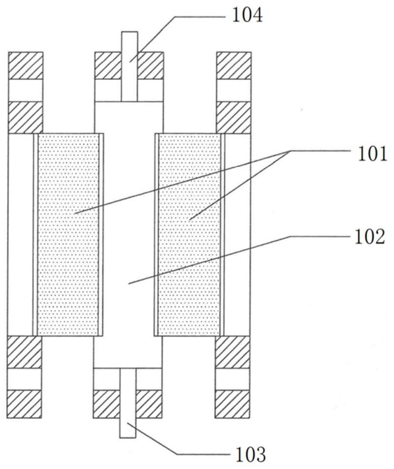
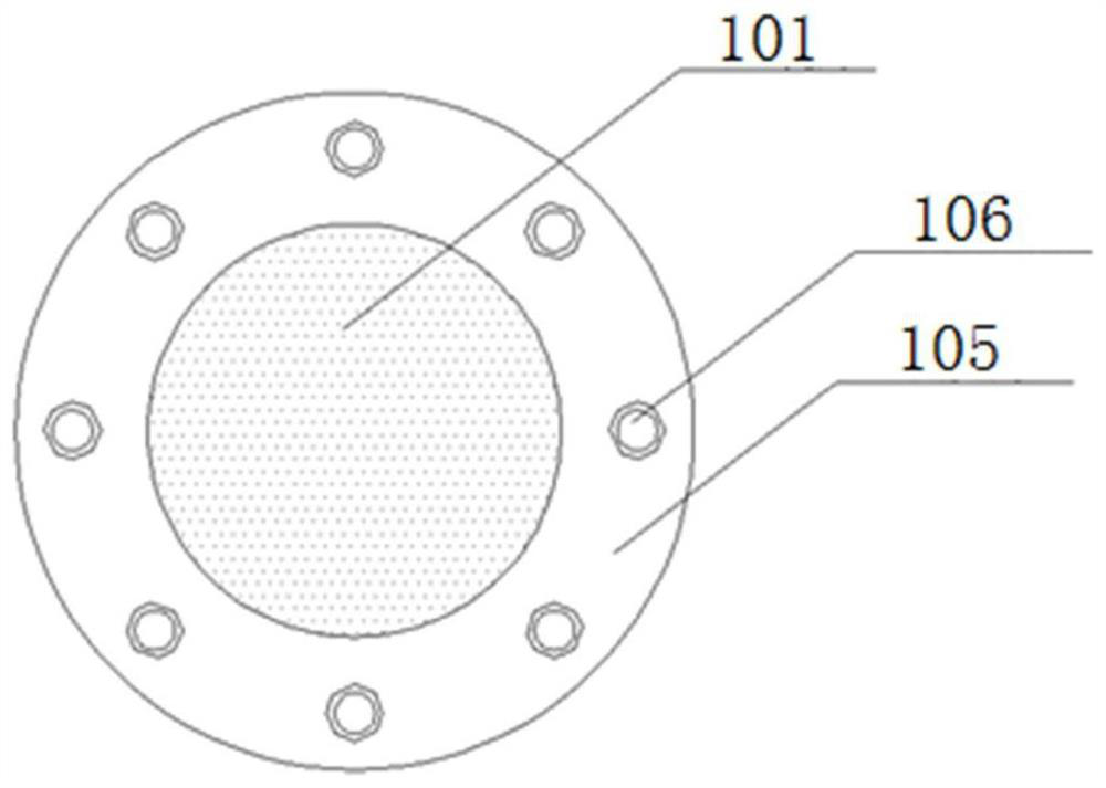
[0025] A sight glass for temperature correction of infrared thermometers, see figure 1 , which includes a double-layer mirror glass 101 and a cooling water interlayer 102 arranged between the double-layer mirror glass 101 . The sight glass is fastened by flange connection; the sight glass also includes a cooling water inlet 103 and a cooling water outlet 104 .

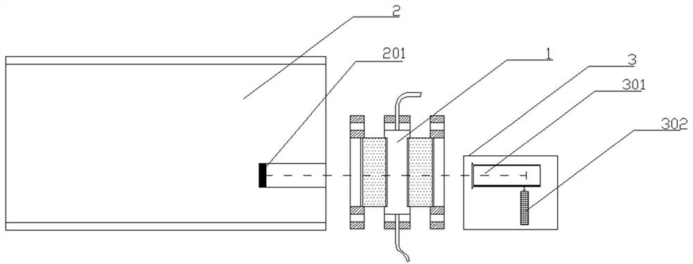
[0026] A calibration device for an infrared thermometer, see image 3 , including a black body furnace 2, a sight glass 1 and an infrared temperature measuring device 3 which are arranged in sequence in a non-contact manner. The black body furnace is provided with a radiator 201. Cooling water interlayer 102 between mirror glasses 101 (see figure 1 ), the infrared temperature measuring device 3 includes an infrared temperature measuring instrument 301; the infrared rays emitted by the radiator 201 are collected on the infrared pyrometer 301 through the sight glass 1 and are converted into corresponding electrical sig...

Embodiment 2

[0032]The flow rate of cooling water will affect the temperature distribution of cooling water in the sight glass. When the flow rate of cooling water is 1L / min, the actual operating condition of the reduction furnace is used as the boundary condition, and the temperature distribution of the sight glass water is calculated by the fluid mechanics simulation software. From the simulation results, there is an obvious temperature gradient distribution in the cooling water of the sight glass, see Figure 4 If the cooling water flow is too small, the temperature measurement error will be caused due to the excessive cooling water temperature gradient. The reasonable cooling water flow should be 5~10L / min.

[0033] Because the cooling water has the effect of absorbing infrared rays, that is, part of the energy emitted by the silicon rod is absorbed by the cooling water after passing through the sight glass, so the measured temperature of the infrared thermometer is lower than the actua...

Embodiment 3

[0039] According to the actual operation state of the reduction furnace, make such as image 3 The calibration device of the infrared thermometer needs to adjust the position of the infrared thermometer 301 when the temperature of the infrared thermometer is calibrated. When the displayed temperature of the infrared thermometer 301 reaches the maximum value, the position of the infrared thermometer 301 is fixed. When the lens of the infrared thermometer 301 is facing the radiator 201, the specific correction method is as follows:

[0040] (1) Set the calibration device according to image 3 Fix as shown, start the black body furnace 2 and set the temperature to 1000°C;

[0041] (2) Turn on the cooling water of the sight glass 1, so that the two pieces of sight glass 101 are filled with water, and the water flow in the cooling water interlayer 102 is stabilized. At this time, the temperature of the cooling water is 30°C, and the flow rate of the cooling water is 6L / min ;

[...


PUM

PropertyMeasurementUnit
emissivityaaaaaaaaaa

Abstract

The invention discloses a sight glass used for temperature correction of an infrared thermometer; and also discloses a correction device for an infrared thermometer, which comprises a black body furnace, a sight glass and an infrared temperature measuring device arranged at intervals in sequence. A radiator is arranged in the furnace, the sight glass comprises a double-layer sight-glass glass and a cooling water interlayer arranged between the double-layer sight-glass glasses, and the infrared temperature measuring device comprises an infrared thermometer; the invention also discloses an infrared thermometer. Thermometer calibration method. Through the calibration of the infrared thermometer, the error between the measured temperature and the actual temperature of the silicon rod can be controlled within ±3°C, and the accurate measurement of the temperature of the silicon rod in the reduction furnace can be realized, which can meet the requirements of the surface of the silicon rod during the production of zone melting silicon. The requirements of accurate and stable temperature control; the function of the sight glass is to simulate the measurement conditions of the infrared thermometer when measuring the production temperature of polysilicon or district melting silicon in the reduction furnace, so that the calibration environment is consistent with the actual measurement environment, and the infrared thermometer measures the temperature. Accuracy and Precision.

Description

technical field [0001] The invention relates to a calibration device and a calibration method for a thermometer, in particular to a calibration device and a calibration method for an infrared thermometer. Background technique [0002] In the production process of polysilicon produced by the Siemens method, the surface temperature of the silicon rod is an important control parameter. A reasonable control of the surface temperature of the silicon rod can not only ensure a good surface morphology of the silicon rod, but also control the reduction power consumption at a lower level. , while avoiding production accidents caused by abnormal temperature. At present, domestic solar-grade polysilicon production enterprises mostly judge the temperature based on the surface color of the silicon rod. This method requires high experience of personnel, and cannot obtain quantitative data; the second is to use high-temperature infrared measurement, this measurement method can Quantitative...

Claims


Application Information

Patent Timeline
Patent Type & Authority Patents(China)
IPC IPC(8): G01J5/0801G01J5/53G01J5/80G01J5/90
CPCG01J5/0803G01J5/80
Inventor 高召帅李钊于跃姜浩李福中沈棽
Owner 江苏鑫华半导体科技股份有限公司
Why Eureka
Try Eureka