Method for calculating convective heat transfer coefficient of hydrostatic rotary table

A technology of convective heat transfer coefficient and rotary table, which is applied in calculation, computer-aided design, electrical digital data processing, etc., can solve problems such as oil film heat generation, large temperature rise, uneven deformation of work table, thermal deformation of work table, etc. , to achieve the effects of increasing productivity, increasing running time, improving running accuracy and stability

Inactive Publication Date: 2018-06-08
HARBIN UNIV OF SCI & TECH
View PDF5 Cites 2 Cited by
  • Summary
  • Abstract
  • Description
  • Claims
  • Application Information

AI Technical Summary

Problems solved by technology

However, under extreme working conditions, the thermal deformation of the static pressure rotary table is obvious, because the heat generated by the oil film increases greatly under extreme working conditions, which will lead to uneven temperature changes of the workbench, which will cause thermal deformation of the workbench
In addition, the convective heat transfer of the static pressure rotary table is different under different extreme working conditions, which further leads to uneven deformation of the table

Method used


Image

  • Method for calculating convective heat transfer coefficient of hydrostatic rotary table
  • Method for calculating convective heat transfer coefficient of hydrostatic rotary table
  • Method for calculating convective heat transfer coefficient of hydrostatic rotary table

Examples


Embodiment Construction

[0010] It can be achieved through the following technical solutions:

[0011] The calculation of the convective coefficient of the workbench can be divided into two parts: the upper surface and the side, that is, the calculation of the upper surface convective heat transfer coefficient can be compared to the fluid flowing through the horizontal plate, and the calculation of the side convective heat transfer coefficient can be compared to the fluid passing through the horizontal direction. Vertical flat wall.

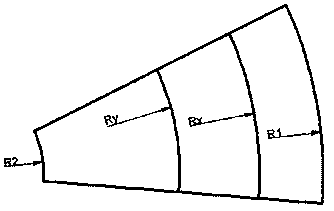
[0012] Because the radius of the rotary table is relatively large, the surface linear velocity at the outer edge of the rotary table and the center of rotation is very different, so the flow state of the air near the surface of the rotary table is also different, so the convection between the rotary table and the air The difference in heat intensity is relatively large. In order to obtain simulation results closer to the actual working conditions, the upper surface of t...


PUM


Abstract

The invention relates to a method for calculating the convective heat transfer coefficient of a hydrostatic rotary table. The method comprises the steps of calculating convective heat transfer coefficients of the rotary table and a base, wherein the calculation of the convective heat transfer coefficient of the rotary table can be divided into two parts: the calculation of the upper surface and the calculation of side faces, that is, the calculation of the convective heat transfer coefficient of the upper surface can be compared to fluid flowing through a horizontal plate and the calculation of the convective heat transfer coefficient of the side faces can be compared to the fluid horizontally flitting through vertical planar walls; the convective heat transfer coefficient of each part ofthe upper surface of the rotary table is calculated by using an area trisectioning method, that is, the rotary table has a large radius and the heat emission coefficients at different positions at thesame rotation speed have large differences, so that the upper surface of the rotary table is divided into three parts and the average value is calculated through averaging to serve as the convectiveheat transfer coefficient of the rotary table; and the convective heat transfer of the base is divided into two parts: the natural convective heat transfer of the vertical planar wall surface and thenatural convective heat transfer of the horizontal plates, hot faces of which are downwards arranged, to calculate the convective heat transfer coefficient of the base.

Description

technical field [0001] The invention relates to a method for calculating the convective heat transfer coefficient of a static pressure rotary table, in particular to a method for calculating the convective heat transfer coefficient of a static pressure rotary table with double rectangular cavities. Background technique [0002] Due to the advantages of low power consumption, long life, stable operation and high precision, the hydrostatic rotary table has become the core component of large-scale CNC equipment. In recent years, with the continuous advancement of science and technology, higher and higher requirements have been put forward for the machining accuracy, machining size, machining speed and carrying capacity of machine tools. However, under extreme working conditions, the thermal deformation of the static pressure rotary table is obvious, because the heat generated by the oil film increases greatly under extreme working conditions, which will lead to uneven temperatu...

Claims


Application Information

Patent Timeline
Patent Type & Authority Applications(China)
IPC IPC(8): G06F17/50
CPCG06F30/20G06F2119/08
Inventor 于晓东曲航郑旭航李代阁袁腾飞
Owner HARBIN UNIV OF SCI & TECH
Why Eureka
Try Eureka