A Design Method for Rotor Core of Permanent Magnet Synchronous Motor

A permanent magnet synchronous motor and rotor core technology, which is applied in the manufacture of motor generators, stator/rotor bodies, electromechanical devices, etc. problems such as a large value range, to achieve the effect of being beneficial to intelligent manufacturing, easy application and promotion, and improving quality control

Active Publication Date: 2019-11-12
SHANGHAI MOTOR SYST ENERGY SAVING ENG TECH RES CENT +2
View PDF8 Cites 0 Cited by
  • Summary
  • Abstract
  • Description
  • Claims
  • Application Information

AI Technical Summary

Problems solved by technology

[0004] In order to improve the sine of the air gap magnetic density, the surface of each magnetic pole of the rotor is designed as a non-circular structure. In this regard, many scholars have made various design attempts: in the invention patent "a built-in sinusoidal surface permanent magnet Motor Rotor" (Patent No.: CN102857000A) adopts the design scheme of eccentric circle, which is a relatively common design method, which is used to approximate the equivalent sinusoidal flux density; in the utility model "a self-starting sine wave current In the "Three-phase Rare Earth Permanent Magnet Synchronous Motor" (Patent No.: CN201478968U), the rotor surface is designed in sections. This design method approximates the equivalent uneven sinusoidal air gap through the combination of arcs and straight lines; in the invention patent " In the "motor and compressor with the motor" (patent number: CN103516165A), the stepped rotor core surface design method is adopted to achieve the purpose of improving the sine degree of the motor; in the invention patent "rotor ideal sine wave air gap magnetic field permanent magnet synchronous In "Motor", the method described is the air gap curve under the ideal state, and the air gap width is studied, but the magnetic flux saturation of the core is not involved
These patents use rotor surfaces of different shapes to equivalently obtain the sinusoidal distribution of magnetic density. They are all approximate design methods, and the calculation models are not accurate enough. In addition, some methods have many types of parameters, and each parameter has a large range of values. Facilitate parameter selection and design

Method used


Image

  • A Design Method for Rotor Core of Permanent Magnet Synchronous Motor
  • A Design Method for Rotor Core of Permanent Magnet Synchronous Motor
  • A Design Method for Rotor Core of Permanent Magnet Synchronous Motor

Examples


Embodiment Construction

[0030] In order to make the present invention more comprehensible, preferred embodiments are described in detail below with accompanying drawings.

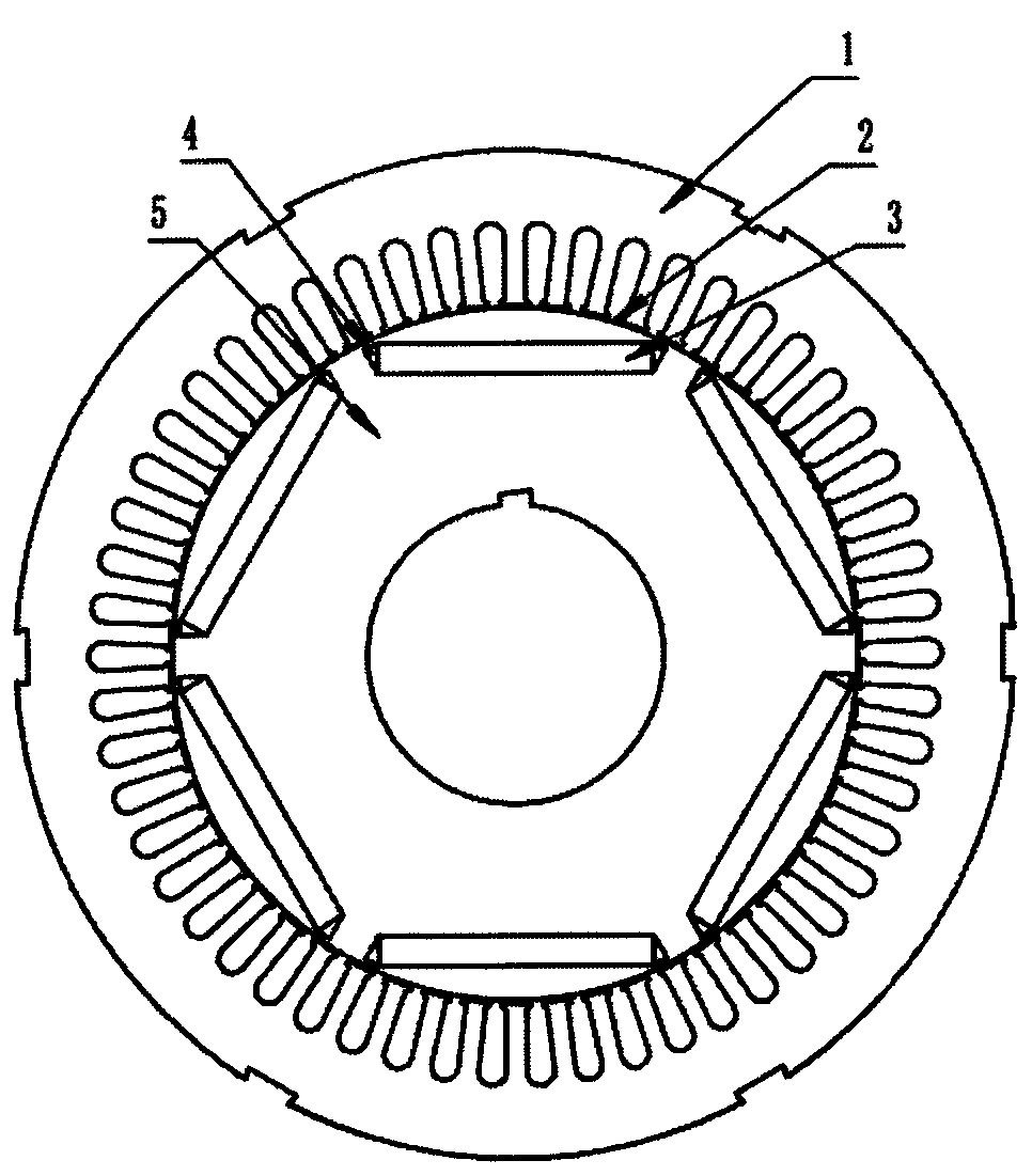
[0031] The present invention improves a permanent magnet synchronous motor rotor core design method, comprising the following steps:

[0032] The magnetic permeability of the air is much smaller than that of the silicon steel sheet. During the operation of the motor, the magnetic potential in the magnetic circuit is mainly concentrated in the air gap with a small magnetic permeability. However, in order to improve the utilization rate of the silicon steel sheet material and improve the The power density of the motor, the magnetic density in the iron core is generally near the knee point, and is in a slightly saturated state, especially in the water-cooled motor, because the heat dissipation effect is better, so in order to reduce the volume or reduce the cost, the volume of the motor is more Small, in order to maintain the output ...


PUM


Abstract

The invention relates to a design method of a rotor iron core of a permanent magnet synchronous motor. The design method of the rotor iron core is convenient in calculation and can increase air gap flux density sine effectively. The advantages are as follows: the design method of the rotor iron core of the permanent magnet motor can effectively lower harmonic wave of the air gap flux density of the motor, lower stray loss of the motor, improve the motor efficiency and reduce vibration and noise of the motor, the design method has a wide application range and can be applicable to various inner-rotor embedded permanent magnet synchronous motors, and parameters of a formula can be selected flexibly, the minimum of air gap can be selected freely according to the type and performance of the motor, different air gap minimums are corresponding to different rotor surface curves, and each curve can achieve a goal of lowering the motor flux density harmonic wave.

Description

technical field [0001] The invention relates to a rotor core design method for reducing the harmonic content of the air gap flux density of an inner rotor embedded permanent magnet synchronous motor, belonging to the technical field of permanent magnet synchronous motors. Background technique [0002] Permanent magnet synchronous motor is a high-efficiency sinusoidal AC motor with the characteristics of small size, high efficiency and high power factor. It is widely used in textile, petroleum, transportation and other industries. [0003] Existing permanent magnet synchronous motors usually use circular rotor punching laminations to form a rotor core, and then process the air gap between the stator and rotor cores through a lathe. Due to the limitations of lathe processing, the outer surface of the rotor of this motor is circular. , the stator-rotor air gap is a uniform air gap. During the operation of the permanent magnet synchronous motor, the rotor speed is the same as t...

Claims


Application Information

Patent Timeline
Patent Type & Authority Patents(China)
IPC IPC(8): H02K15/03
CPCH02K15/03H02K2213/03
Inventor 姚丙雷王鸿鹄周洪发
Owner SHANGHAI MOTOR SYST ENERGY SAVING ENG TECH RES CENT
Why Eureka
Try Eureka