Fuel injection valve and orifice plate
A technology of fuel injection valves and injection holes, which is applied in the direction of fuel injection devices, charging systems, machines/engines, etc., which can solve the problems of reduced layout of passageways and difficulties in multi-injection holes, and achieve roughly equal strength
- Summary
- Abstract
- Description
- Claims
- Application Information
AI Technical Summary
Problems solved by technology
Method used
Image
Examples
Embodiment approach 1
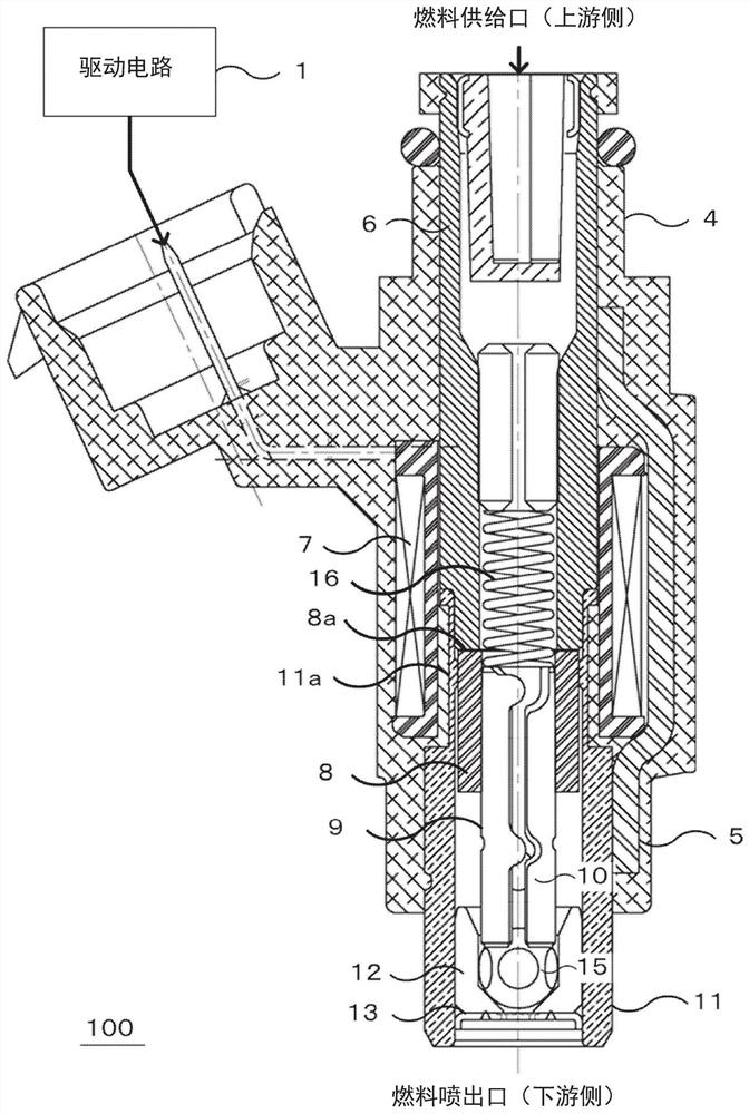
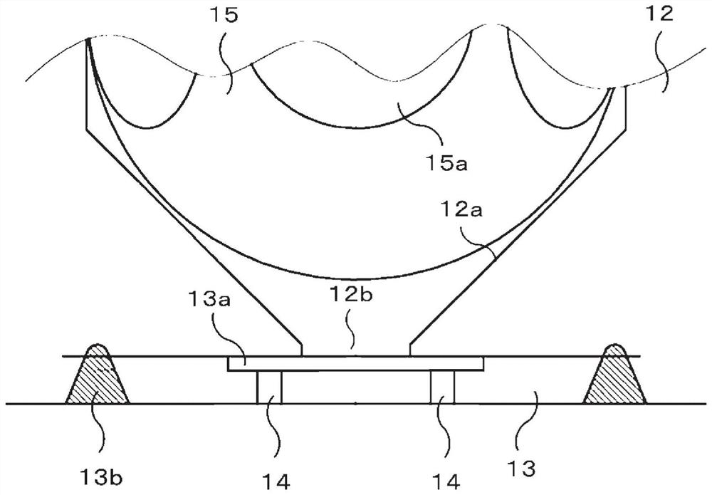
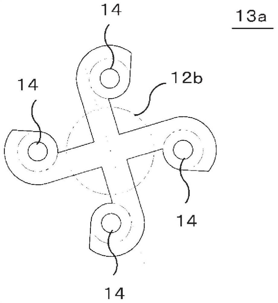
[0033] figure 1 A cross section of the fuel injection valve according to the embodiment of the present invention is shown. In the fuel injection valve 100, the fuel introduced from the fuel supply port is atomized and discharged from the injection port in the form of a spray. The fuel injection valve 100 is composed of a drive circuit 1, a solenoid device 4, a housing 5, a core 6, an armature 8, a piston 9, a valve body 11, a valve seat 12, an orifice plate 13, and the like. In the drive circuit 1 of the fuel injection valve 100, an operation signal and a stop signal are sent from the engine control device. The drive circuit 1 supplies drive current to the solenoid device 4 based on these signals, and drives the piston 9 . The drive current generates magnetic flux in the magnetic circuit composed of the armature 8 , the iron core 6 , the case 5 , and the valve main body 11 . The valve seat 12 is arranged on the downstream side of the piston 9 .
[0034] The case 5 correspo...
Embodiment approach 2
[0050] Figure 9 The recess 13a in the fuel injection valve 100 according to Embodiment 2 is shown. The cylindrical portion 19 has a diameter D1. In order to create a uniform swirling fuel flow, it is preferable that the fuel flow 21 directly entering the cylindrical part 19 from the introduction part 18 and the fuel flow 22 passing through the rotating part 20 from the introducing part 18 do not conflict with the swirling fuel flow formed in the cylindrical part 19 smoothly flow into the cylindrical part 19. That is, it is necessary to make the inflow area of each fuel into the cylindrical portion 19 smaller than the radius D1 / 2 of the cylindrical portion.
[0051] In the fuel injection valve 100 according to the present embodiment, as Figure 10 As shown, the area directly entering the cylindrical portion 19 from the introduction portion 18 has a width W1-W2, and the area where the fuel flow through the rotating portion 20 flows into the cylindrical portion 19 has a wid...
Embodiment approach 3
[0054] Figure 11A A plan view showing the recess 13a in the fuel injection valve according to the third embodiment. Figure 11B A cross-sectional view showing the recess 13a in the fuel injection valve according to the third embodiment. In the configurations of Embodiments 1 and 2, since the fuel flow flowing into the cylindrical portion directly enters the injection hole 14, the fuel may be injected with insufficient rotation, and the thinning of the liquid film may not be sufficiently performed. Therefore, in Embodiment 3, the bottom surface of the cylindrical portion 19 is made deeper than the bottom surfaces of the introduction portion 18 and the rotating portion 20 . As a result, the fuel flow 21 directly entering the cylindrical portion 19 from the introduction portion 18 and the fuel flow 22 passing through the rotating portion 20 from the introduction portion 18 flow into the cylindrical portion and then flow toward the bottom surface of the cylindrical portion, so t...
PUM
 Abstract
Description
Claims
Application Information
 - R&D
- Intellectual Property
- Life Sciences
- Materials
- Tech Scout
- Unparalleled Data Quality
- Higher Quality Content
- 60% Fewer Hallucinations
Browse by: Latest US Patents, China's latest patents, Technical Efficacy Thesaurus, Application Domain, Technology Topic, Popular Technical Reports.
© 2025 PatSnap. All rights reserved.Legal|Privacy policy|Modern Slavery Act Transparency Statement|Sitemap|About US| Contact US: help@patsnap.com


