Bidirectional in-situ blocking remediation system for nitrogen pollution migration of shallow groundwater

A technology for repairing systems and groundwater, which is applied to water pollutants, contaminated groundwater/leachate treatment, water/sewage treatment, etc., and can solve the problems of difficult-to-apply large-scale contaminated site restoration, unfavorable post-maintenance, and reduced restoration efficiency, etc. problems, to achieve the effect of reducing the probability of groundwater bypass and silting, avoiding deep excavation and backfilling, and zero maintenance costs in the later period

Active Publication Date: 2018-06-12
TONGJI UNIV
View PDF6 Cites 19 Cited by
  • Summary
  • Abstract
  • Description
  • Claims
  • Application Information

AI Technical Summary

Problems solved by technology

[0008] The above-mentioned inventive devices and equipment all require power facilities or ground facilities, and there are many constructions, and the process and operation steps require precision, which is not conducive to later maintenance; in the process of use, water needs to be pumped, which is likely to cause changes in the hydraulic characteristics of groundwater and stratum structures. Reduced repair efficiency and ground subsidence in different degrees; the above-mentioned equipment is a single integrated structure, which is difficult to apply to the repair of large-scale contaminated sites

Method used


Image

  • Bidirectional in-situ blocking remediation system for nitrogen pollution migration of shallow groundwater
  • Bidirectional in-situ blocking remediation system for nitrogen pollution migration of shallow groundwater
  • Bidirectional in-situ blocking remediation system for nitrogen pollution migration of shallow groundwater

Examples


Embodiment

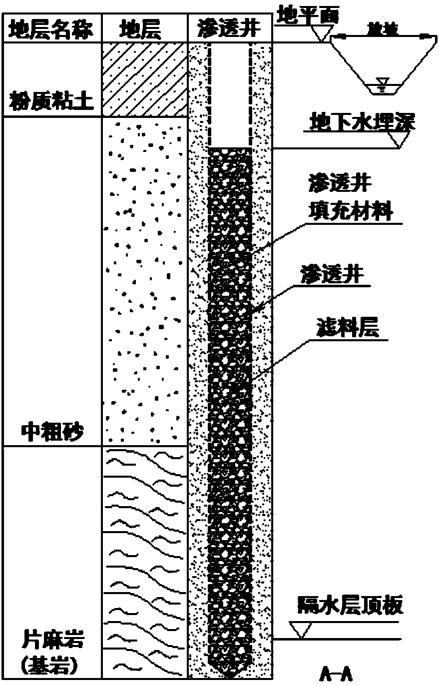
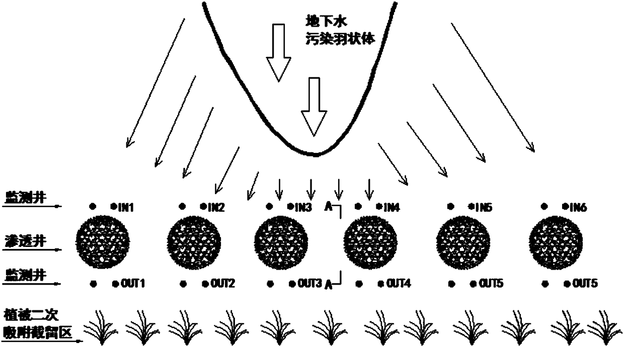
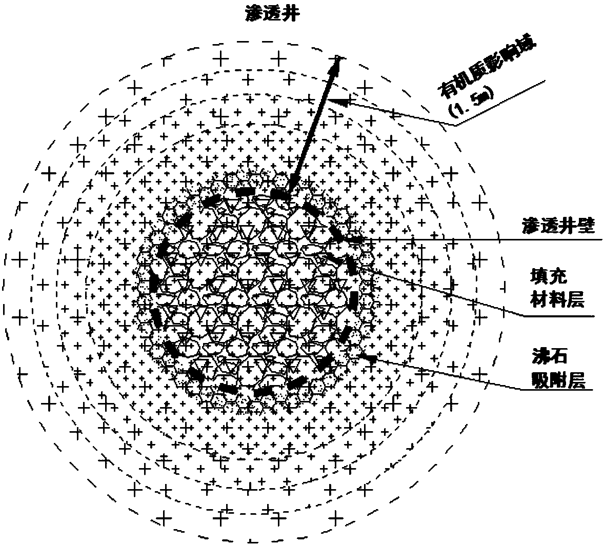
[0035] A two-way in-situ blocking repair system for nitrogen pollution migration in shallow groundwater, referring to Figure 1-3 , used to remove pollutants in underground polluted water bodies, including a number of infiltration wells arranged in a straight line, the inside of the infiltration well is filled with repair fillers, the outside of the infiltration well is provided with a filter layer, and the walls of the infiltration well are covered with organic matter penetration hole.

[0036] Preferably, the permeation well is made of PVC-U or stainless steel, with a diameter of 160-200 mm, and the center interval of the permeation well is 240-340 cm. The permeation well is buried in a straight line perpendicular to the direction of the pollution plume, and its length is 2 to 5 times the widest point. The repair filler is functional carbon source material and sponge iron, and the functional carbon source material is a solid phase medium with a density greater than 1.0mg m ...


PUM

PropertyMeasurementUnit
diameteraaaaaaaaaa
lengthaaaaaaaaaa
densityaaaaaaaaaa

Abstract

The invention relates to a bidirectional in-situ blocking remediation system for nitrogen pollution migration of shallow groundwater. The system is used for groundwater pollution control. The system mainly comprises a permeation well, a remediation filler, a filter material layer, a vegetation secondary adsorption interception area and monitoring wells; the permeation well is linearly buried perpendicular to a pollution feather-shaped body, and a shallow water-bearing stratum is exposed; organic mater permeation holes are formed in the positions, parallel to cylinder generatrices, of the wellwall at equal intervals; the remediation filler is located in the well; the outer side of the well is coated with the filter material layer; the monitoring wells are located on the two sides of the permeation well; and the vegetation secondary adsorption interception area is located on the remediation water outlet side of the permeation well. Compared with the prior art, the system has the advantages that a ground device and a power facility are not needed, and the construction, operation and maintenance cost is low; construction is easy, and difficulties in large-scale PRB excavation and earthwork are overcome; disturbance on the groundwater environment is reduced; biodegradation, physical adsorption, chemical reduction and phytoremediation are integrated, and therefore the groundwater remediation effect is enhanced; the nitrogen pollution migration in a lateral runoff and a vertical seepage of underground water can be blocked in a bidirectional mode, and the application prospect is wide.

Description

technical field [0001] The invention belongs to the field of groundwater pollution control, in particular to a two-way in-situ blocking repair system for nitrogen pollution migration in shallow groundwater. Background technique [0002] In recent years, groundwater nitrate pollution has become widespread. In response to this situation, domestic and foreign scholars have conducted extensive research and achieved many research results. Among them, in-situ remediation technology is one of the methods commonly used in academia and engineering circles. The more commonly used in-situ treatment technologies for groundwater include injection (air disturbance, in-situ chemical oxidation / reduction, biological aeration, circulation well) and There are two types of permeable reactive walls (PRB). [0003] Injection in-situ remediation technology mainly injects substances such as liquid and gas into the groundwater layer to promote direct chemical reactions between the injected substan...

Claims


Application Information

Patent Timeline
Patent Type & Authority Applications(China)
IPC IPC(8): C02F3/34C02F3/32C02F101/16C02F103/06
CPCC02F1/001C02F1/281C02F3/32C02F3/34C02F2101/16C02F2103/06
Inventor 张雯周念清夏学敏
Owner TONGJI UNIV
Why Eureka
Try Eureka