Method for removing sulfur oxides and nitrogen oxides in catalytic cracking regeneration flue gas

A technology for regenerating flue gas and catalytic cracking, which is applied in chemical instruments and methods, separation methods, and air quality improvement. The effect of pollutant treatment process

Active Publication Date: 2013-01-30
CHINA PETROLEUM & CHEM CORP +1
View PDF10 Cites 19 Cited by
  • Summary
  • Abstract
  • Description
  • Claims
  • Application Information

AI Technical Summary

Problems solved by technology

From the existing technologies, the removal of sulfur oxides in flue gas and hydrogen sulfide in dry gas is carried out separately, and there is no report on the technology of treating flue gas and dry gas together.

Method used


Image

  • Method for removing sulfur oxides and nitrogen oxides in catalytic cracking regeneration flue gas
  • Method for removing sulfur oxides and nitrogen oxides in catalytic cracking regeneration flue gas

Examples


preparation example Construction

[0049] Catalyst preparation method:

[0050] Will Al 2 o 3 ·H 2 O(pseudoboehmite), Ce(NO 3 ) 3 , ZrO(NO 3 ) 2 , put it in a beaker according to the ratio of m(Al):m(Ce):m(Zr)=85:5:10, add deionized water to make a slurry, stir and age for 2 hours, then add appropriate amount of scallop powder to form The semi-solid is further extruded into Φ1mm cylindrical strips, dried at 110°C, and then baked at 700°C for 4 hours, and cut into Φ1×2mm columnar particles as carriers for later use.

[0051] H 2 PtCL 6 ·6H 2 The aqueous solution of O impregnated the carrier twice, and each time was dried at 110°C and calcined at 650°C for 4 hours to obtain catalyst A. Based on the total weight of the catalyst, the weight percentage of PtO in the catalyst A is 0.40wt%. Before the catalyst was used, it was heated under H at the reaction temperature 2 Pre-reduction in the atmosphere for half an hour.

[0052] La(NO 3 ) 3 .6H 2 The aqueous solution of O impregnated the carrier twice,...

Embodiment

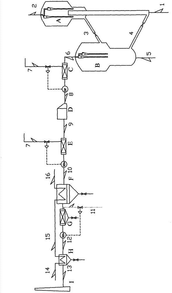
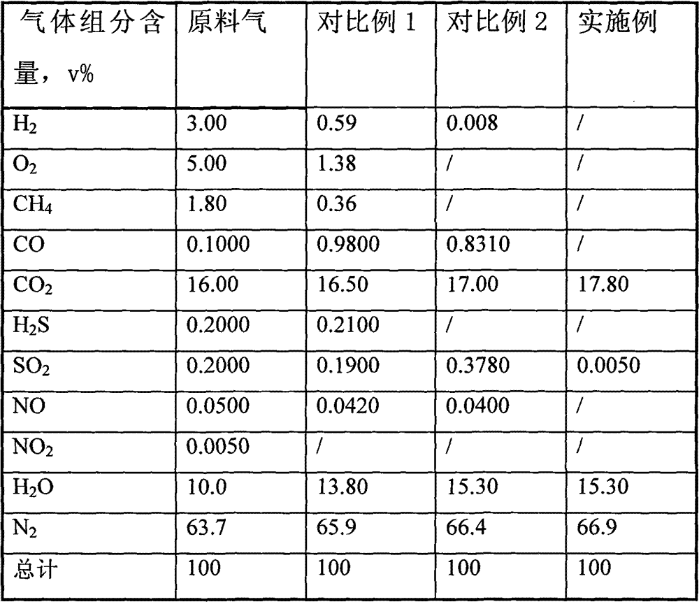
[0060] Two fixed-bed reactors (Φ20×600mm) are connected in series. The former reactor I is filled with catalyst A, with a loading capacity of 5.0g. The reaction is carried out under the conditions of normal pressure and reaction temperature of 650°C, and the weight hourly space velocity is 48h. -1 . The latter reactor II is loaded with catalyst B, the catalyst loading amount is 5.0 g, and the reaction is carried out under the conditions of normal pressure and reaction temperature of 500°C. The tail gas composition when the reaction reaches equilibrium is shown in Table 1.

[0061] Table 1

[0062]

[0063] It can be seen from Table 1 that the reactor in Comparative Example 1 was not filled with catalyst, and after the two streams of flue gas and reducing gas contacted at 650°C, the oxygen in the feed gas was consumed and the carbon monoxide content in the tail gas increased. In comparative example 2, due to the H in the feed gas 2 S is oxidized during the reaction, so SO...


PUM


Abstract

The invention relates to a method for removing sulfur oxides and nitrogen oxides in catalytic cracking regeneration flue gas. According to the invention, regeneration flue gas discharged from a catalytic cracking regeneration device is delivered into a high-temperature zone reactor, and is subjected to a reaction at a catalyst bed layer with a reducing gas under a temperature of 620-690 DEG C; sulfur oxides, nitrogen oxides and oxygen in the flue gas are subjected to the reaction with the reducing gas, such that gas-state elemental sulfur, nitrogen and water vapor are produced; after the reaction, a mixed flue gas containing gas-state sulfur is delivered into a flue gas turbine, and is delivered into a middle-temperature zone reactor; under a temperature of 500-550 DEG C, the mixed flue gas is subjected to a reaction with reducing gas, such that gas-state elemental sulfur, nitrogen and water vapor are produced; after the reaction, a mixed gas is delivered into a waste heat boiler and is subjected to heat exchange until a temperature is 150-250 DEG C, and liquid-state sulfur is recovered; and the material is subjected to heat exchange in a cooling device, and solid-state sulfur is recovered. With the method provided by the invention, a subsequent desulphurization treatment process of sulfur-containing flue gas of a catalytic cracking device is eliminated, a catalytic cracking device pollutant controlling process is simplified, and powerful guarantee is provided for clean production of the catalytic cracking device.

Description

technical field [0001] The present invention relates to a method for waste gas treatment, more specifically, relates to a method for removing sulfur oxides and / or nitrogen oxides from regenerated flue gas discharged from a regenerator in a catalytic cracking unit, and recovering elemental sulfur. Background technique [0002] The catalytic cracking catalyst is circulated between the reactor and the regenerator. Usually, when leaving the reactor, the catalyst contains about 3-10wt% coke, and the deposited coke must be burned with oxygen in the air in the regenerator to restore catalytic activity. . The coke deposited on the catalyst is mainly a reaction condensate, and its main components are carbon and hydrogen. When the cracking raw material contains sulfur and nitrogen, the coke also contains sulfur and nitrogen. The carbon-deposited catalyst reacts with oxygen to generate CO 2 , CO and H 2 O, regeneration flue gas also contains SOx (SO 2 , SO 3 ) and NOx (NO, NO 2 )...

Claims


Application Information

Patent Timeline
Patent Type & Authority Applications(China)
IPC IPC(8): B01D53/90B01D53/60C01B17/04
CPCY02A50/20Y02P20/129
Inventor 郭大为张久顺毛安国谢朝钢傅军王巍于敬川
Owner CHINA PETROLEUM & CHEM CORP
Why Eureka
Try Eureka