Check patentability & draft patents in minutes with Patsnap Eureka AI!

Pressure sensor temperature drift compensation circuit and compensation method

A technology of pressure sensor and temperature drift compensation, which is applied in the direction of measuring fluid pressure, instruments, measuring force, etc. It can solve the problems that the temperature coefficient of sensor sensitivity cannot be accurately compensated, and the calculation results are not necessarily accurate and different, and achieve simple circuit structure and compensation High precision and simple effect

Active Publication Date: 2018-06-12
48TH RES INST OF CHINA ELECTRONICS TECH GROUP CORP
View PDF5 Cites 7 Cited by
  • Summary
  • Abstract
  • Description
  • Claims
  • Application Information

AI Technical Summary

Problems solved by technology

However, due to the difference in process methods, the temperature characteristics of each pressure-sensitive Wheatstone bridge will be different, and the patent CN105784215A mainly realizes the temperature compensation of different types of sensors by changing the number of series diodes, and the voltage drop of the diode 2CK4148 used in it varies with temperature Change rate ΔV t ≈-2.5mV / ℃, and approximately linear, in the case of 10V constant voltage power supply, the temperature coefficient of the pressure sensor that can be compensated is T C ≈n*0.025%FS / ℃ (n is the number of diodes), there are two main disadvantages in this method, the first disadvantage is that the calculation method of the number of diodes is relatively complicated, and the calculation results are not necessarily accurate; the second disadvantage is that it cannot Accurately compensate the temperature coefficient of sensor sensitivity, because the number of diodes can only be an integer, so it is either under-compensated or over-compensated. The product can theoretically achieve the sensitivity temperature drift after compensation β=±0.0125% FS / ℃, which obviously cannot meet the current requirements. Wide temperature range and high precision requirements in many applications

Method used


Image

  • Pressure sensor temperature drift compensation circuit and compensation method
  • Pressure sensor temperature drift compensation circuit and compensation method
  • Pressure sensor temperature drift compensation circuit and compensation method

Examples


Embodiment Construction

[0022] The present invention will be further described below in conjunction with the accompanying drawings and specific embodiments.

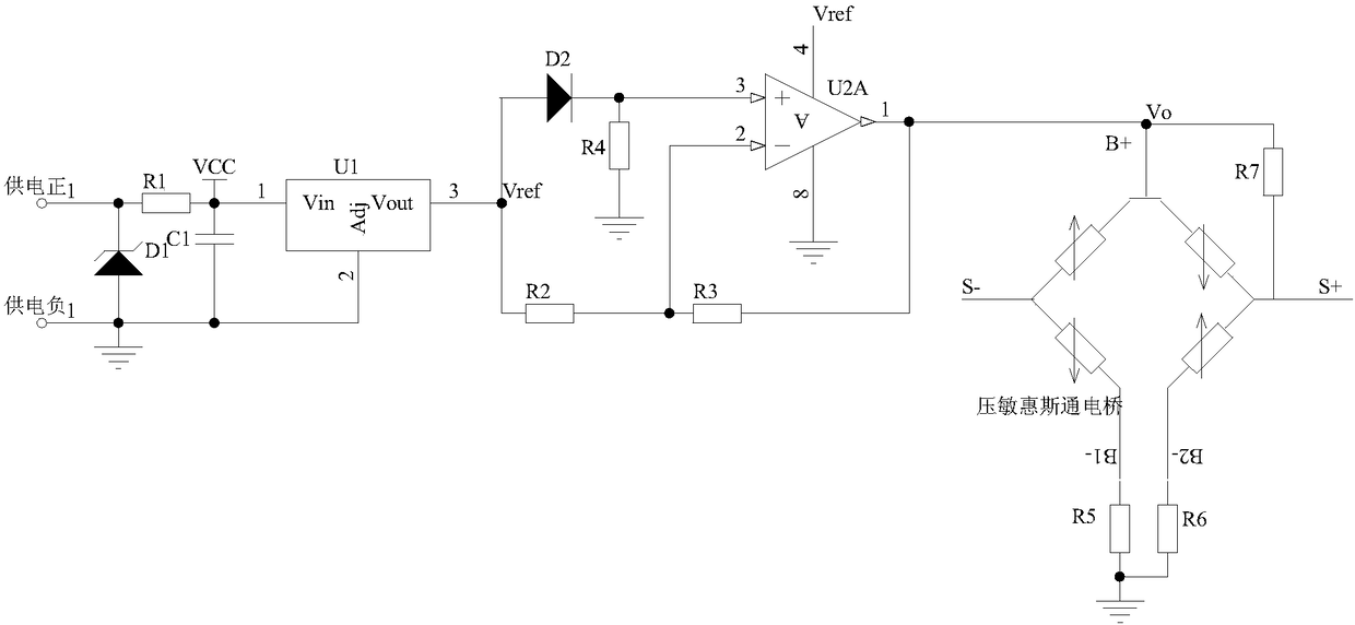
[0023] Such as figure 1 As shown, the pressure sensor temperature drift compensation circuit of this embodiment includes a subtractor, wherein the subtractor includes an operational amplifier U2A, a diode D2, a first resistor R2, a second resistor R3 and a third resistor R4, and the output of the operational amplifier connected to the input terminal of the pressure-sensitive Wheatstone bridge of the pressure sensor, the inverting input terminal of the operational amplifier is connected to the input power supply of the subtractor through the first resistor, and the inverting input terminal and the output terminal of the operational amplifier are connected through the second connected to the resistors, the non-inverting input terminal of the operational amplifier is connected to the ground through the third resistor, and connected to the input po...


PUM


Abstract

The invention discloses a pressure sensor temperature drift compensation circuit, which comprises a subtracter, wherein the subtracter comprises an operational amplifier, a diode, a first resistor, asecond resistor and a third resistor, an output end of the operational amplifier is connected with an input end of a voltage-sensitive Wheatstone bridge, an inverted input end of the operational amplifier is connected with an input power supply of the subtracter through the first resistor, the inverted input end and the output end of the operational amplifier are connected through the second resistor, an in-phase input end of the operational amplifier is connected with the ground through the third resistor and is connected with the input power supply through the diode, a positive electrode ofthe diode is connected with the input power supply, and a negative electrode of the diode is connected with the in-phase input end of the operational amplifier. The invention further discloses a compensation method correspondingly. The compensation method is that the ratio of the second resistor and the first resistor is adjusted so as to enable zero point temperature drift [beta] of a pressure sensor to be equal to abs([alpha]), wherein the [alpha] is a temperature coefficient of output voltage VO of the subtracter. The circuit and method disclosed by the invention has the advantages of improving the compensation accuracy and the like.

Description

technical field [0001] The invention mainly relates to the technical field of pressure measurement, in particular to a pressure sensor temperature drift compensation circuit and compensation method. Background technique [0002] At present, pressure sensors are widely used in aerospace, industry, automotive electronics, artificial intelligence, medicine, meteorology and other fields, and various application fields also put forward higher and higher requirements for their performance indicators. [0003] The most widely used pressure sensors now mainly include diffused silicon piezoresistive pressure sensors and sputtered thin film pressure sensors. The pressure sensors of both principles contain a Wheatstone pressure-sensitive bridge inside, whether it is a diffused silicon resistor or a metal film resistor. All have positive temperature coefficient characteristics. As the temperature rises, its resistance will increase. In the case of constant voltage power supply, as the t...

Claims


Application Information

Patent Timeline
IPC IPC(8): G01L1/00G01L19/04
CPCG01L1/00G01L19/04
Inventor 刘又清金忠谢锋
Owner 48TH RES INST OF CHINA ELECTRONICS TECH GROUP CORP
Features
  • R&D
  • Intellectual Property
  • Life Sciences
  • Materials
  • Tech Scout
  • Unparalleled Data Quality
  • Higher Quality Content
  • 60% Fewer Hallucinations
Learn More