Modularized combined type deodorizing device

A combined and modular technology, applied in chemical instruments and methods, gas treatment, membrane technology, etc., can solve the problems of complex management and maintenance, large footprint, high operating costs, etc., to achieve simple management and maintenance, small footprint , the effect of low operating costs

Active Publication Date: 2018-06-15
BEIJING UNIVERSITY OF CIVIL ENGINEERING AND ARCHITECTURE
View PDF6 Cites 2 Cited by
  • Summary
  • Abstract
  • Description
  • Claims
  • Application Information

AI Technical Summary

Problems solved by technology

[0002] The existing malodorous gas treatment methods mainly include adsorption method, biological absorption, photo-oxygen catalysis, low temperature plasma, catalytic combustion and other processes. Each process only has a better treatment effect on specific malodorous gases. A combinat

Method used


Image

  • Modularized combined type deodorizing device
  • Modularized combined type deodorizing device
  • Modularized combined type deodorizing device

Examples


Embodiment 1

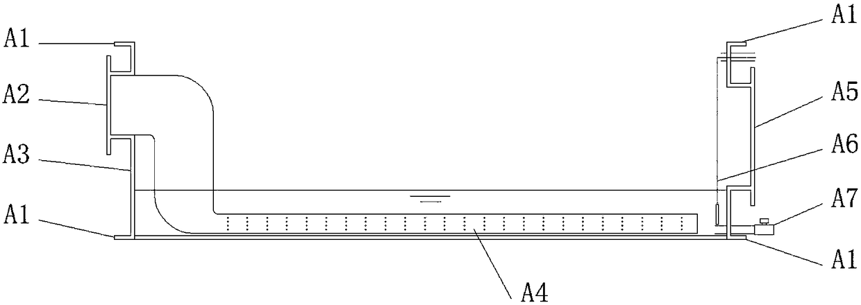
[0053] Figure 7 This is a structural diagram of a modular combined deodorization device provided by Embodiment 1 of the present invention. The device is composed of an aeration module, an I-type filler module and a top cover module. The odorous gas collected centrally is collected from the air inlet of the aeration module. Enter the equipment, after being evenly aerated by the aeration pipe, after contacting with alkaline microorganisms, it enters the I-type packing module; the air distribution plate in the I-type packing module evenly distributes the air and contacts with the microbial packing in the weak acid environment. The pH value and temperature of the packing are The humidity is controlled by the sensor to adjust the spray humidification head; some pollutants are degraded and enter the second-layer I-type filler module, and after evenly distributing the air, they contact the second-layer acidic environment microbial filler. The pH, temperature and humidity of the filler ...

Embodiment 2

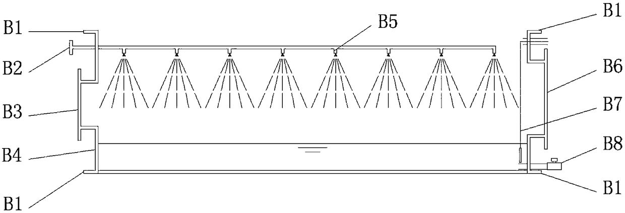
[0055] Figure 8 This is a structural diagram of a modular combined deodorizing device provided in the second embodiment of the present invention. The device is composed of an enhanced washing module, a type I packing module, a dehumidification module, a type II packing module and a top cover module, and the odor is collected in a centralized manner. The gas enters the equipment from the air inlet of the enhanced washing module, and the enhanced washing nozzle sprays alkaline microbial diluent, which reacts with the pollutants in the malodorous gas and absorbs some pollutants; the malodorous gas after the enhanced washing enters the I-type packing module , The air distribution plate evenly distributes the air and contacts with the microbial filler in the weak acid environment. The pH, temperature and humidity of the filler are adjusted by the sensor controlled spray humidification head. Some pollutants are degraded and enter the dehumidification module, after passing through the ...


PUM


Abstract

The invention provides a modularized combined type deodorizing device which comprises a top cover module and an I type filler module and further comprises an aerating module, a reinforced washing module, a dehumidifying module and/or an II type filler module, wherein the I type filler module comprises a fixed flange, a water supplying pipe, a humidifying spray head, an inspection manhole, a temperature-humidity sensor, a pH sensor, a gas distribution plate and a support; the II type filler module comprises a fixed flange, a support, an inspection manhole, a temperature-humidity sensor, a pH sensor, a discharging opening and a gas distribution plate; the aerating module comprises a fixed flange, a gas inlet, an aerating pipe, an inspection manhole, a water level sensor and a water drainingopening; the dehumidifying module comprises a fixed flange, a support, a baffle plate and dehumidifying filter cotton. The device disclosed by the invention can choose different modules to be overlapped and combined according to the gas amount of malodorous gas to be treated; compared with a single technology, the device is more suitable for treating the malodorous gas and has the advantages of small wind pressure loss, low energy consumption, low operation cost, small floor space, convenience in management and maintenance and the like.

Description

Technical field [0001] The invention relates to the technical field of malodorous gas treatment, and in particular to a modular combined deodorizing device. Background technique [0002] The existing malodorous gas treatment methods mainly include adsorption, biological absorption, photo-oxygen catalysis, low-temperature plasma, catalytic combustion and other processes. Each process only has a good treatment effect on specific malodorous gases. When the gas composition is complex, Multiple processes are required to be used in combination. Although multiple process combinations can achieve the emission of malodorous gas in the engineering example, there are problems such as large energy consumption, high operating costs, large area, and complex management and maintenance. Summary of the invention [0003] The embodiment of the present invention provides a modular combined deodorizing device to overcome the problems of the prior art. [0004] In order to achieve the above objective, ...

Claims


Application Information

Patent Timeline
IPC IPC(8): B01D53/84B01D53/85B01D53/26B01D53/04
CPCB01D53/04B01D53/26B01D53/266B01D53/84B01D53/85B01D2251/95B01D2253/102B01D2257/90Y02A50/20
Inventor 刘建伟田洪钰徐嵩
Owner BEIJING UNIVERSITY OF CIVIL ENGINEERING AND ARCHITECTURE
Why Eureka
Try Eureka