Drilling coring equipment by adopting natural composite slurry to drill to achieve effect of rock core coated with mud

A mud and natural technology, applied in drilling equipment, drill pipes, drill pipes, etc., can solve the problem of difficulty in accurately determining the particle composition of sand core samples, affecting the accuracy of sand stratification and geological identification, and drilling sandy soil layers. The core removal rate is not high, which is conducive to wide popularization and application, easy to learn and master, and low equipment performance requirements.

Pending Publication Date: 2018-06-15
长江岩土工程有限公司 +1
View PDF4 Cites 2 Cited by
  • Summary
  • Abstract
  • Description
  • Claims
  • Application Information

AI Technical Summary

Problems solved by technology

The low rate of drilling cores in sandy soil layers has always been one of the main problems affecting the quality of engineering drilling. For some projects that need to study the microstructure of sand layers, the existing techniques and methods are difficult to meet the engineering requirements
[0003] The existing sand core sample collection technology level is low, and the sand core sample collection rate has always been low, mostly below 50%, which affects the sand layer and geological identification accuracy
[0004] Sandy soil core samples are often mixed with mud, it is difficult to accurately determine the particle composition of sandy soil core samples, and repeatedly disturbed in the drilling tool, the sandy soil core samples taken out cannot reflect the original structure of sandy soil

Method used


Image

  • Drilling coring equipment by adopting natural composite slurry to drill to achieve effect of rock core coated with mud
  • Drilling coring equipment by adopting natural composite slurry to drill to achieve effect of rock core coated with mud
  • Drilling coring equipment by adopting natural composite slurry to drill to achieve effect of rock core coated with mud

Examples


Embodiment Construction

[0024] The implementation of the present invention will be described in detail below in conjunction with the accompanying drawings, but they do not constitute a limitation to the present invention, and are only examples. At the same time, the advantages of the present invention are clearer and easier to understand through the description.

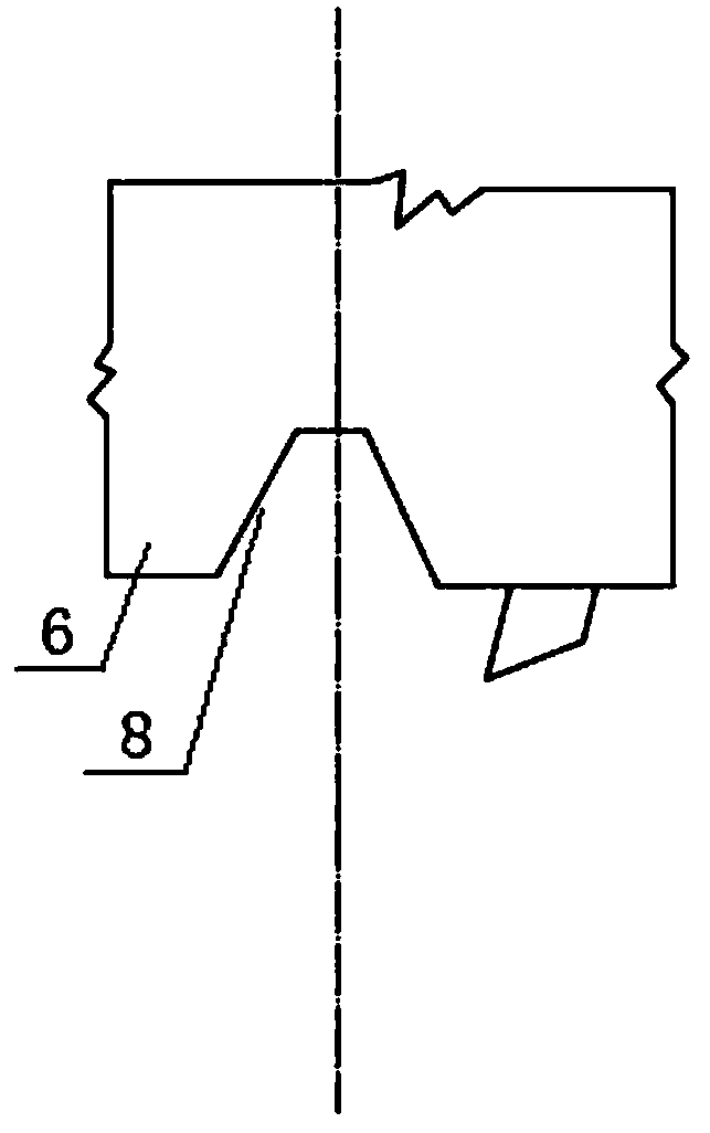
[0025] Referring to the accompanying drawings, it can be seen that the drilling and coring equipment that adopts natural composite mud drilling to achieve the mudcoat-wrapped rock core includes a drill pipe 1 and a core pipe 5, and the drill pipe joint 2 located on the upper part of the core pipe 5 is a joint with a pinball seat , the pinball seat 3 is set in the drill pipe joint 2; when the water-stop marble 7 is set in the pinball seat 3, the upper part of the core pipe 5 is closed, so that the mud pressure in the drill pipe cannot be transmitted to the sand core sample top surface, to avoid sandy soil core samples from falling; the two e...


PUM


Abstract

The invention discloses drilling coring equipment by adopting natural composite slurry to drill to achieve the effect of a rock core coated with mud. The drilling coring equipment comprises a drill pipe and a rock core pipe. A drill pipe joint located on the upper portion of the rock core pipe is a joint with a marble seat, the marble seat is arranged in the drill pipe joint, and when a water stopping marble is arranged in the marble seat, the upper portion of the rock core pipe is sealed; and the two ends of the rock core pipe are connected with a rock core pipe joint and an alloy drill bit,one end of the drill pipe is connected to the interior of the drill pipe joint, and the drill pipe joint is connected with the rock core pipe joint. The defects that in the prior art, the sandy soil rock core sample recovery is lower than 70%, and the undisturbed grain composition and structure of sandy soil cannot be maintained are overcome. The drilling coring equipment has the advantages that the sandy soil rock core sample recovery is sharply improved and can be as high as 100%, and the sampled sandy soil rock core sample is coated with mud, so that the undisturbed grain composition and structure of the sandy soil of the sandy soil rock core sample are maintained.

Description

technical field [0001] The invention relates to the technical field of taking sand core samples, in particular it is a drilling and coring device that adopts natural composite mud drilling to reach mud-coated cores; more specifically, it uses natural composite mud drilling in sand to reach mud Drilling and coring equipment for sandy soil cores wrapped in mud; more specifically, it achieves a substantial increase in the sampling rate of sandy soil cores, up to 100%, and mud coats sandy soil core samples to keep sandy soil core samples Drilling and coring equipment for undisturbed particle gradation and structure of sandy soil. Background technique [0002] Sandy soil is a common loose soil in Quaternary strata, which is granular, has no cohesive force, is easily broken under the condition of no confining pressure, and is easy to form quicksand flowing with water under the action of hydraulic force. The low rate of drilling cores in sandy soil layers has always been one of th...

Claims


Application Information

Patent Timeline
Patent Type & Authority Applications(China)
IPC IPC(8): E21B25/00E21B25/08E21B17/04
CPCE21B17/04E21B25/00E21B25/08
Inventor 马贵生张延仓张涛胡梅生刘海峰候钦礼
Owner 长江岩土工程有限公司
Why Eureka
Try Eureka