
Hydraulic optical fiber sensing system and manufacturing method of inner sensing baseband of hydraulic optical fiber sensing system

An optical fiber sensing system and sensing-based technology, applied in the direction of fluid pressure measurement, liquid level indicator, engine lubrication, etc. by optical methods, can solve the problem of liquid pressure and hydraulic related sensing measurement. There are no literature or patents, etc. problem, to achieve the effect of wide quasi-distributed measurement, high spatial resolution, and wide depth range

Pending Publication Date: 2018-06-15
HEBEI UNIVERSITY
View PDF0 Cites 3 Cited by
  • Summary
  • Abstract
  • Description
  • Claims
  • Application Information

AI Technical Summary

Problems solved by technology

Experimental sensing measurements including direct lateral pressure, temperature, or strain have been reported, but no literature or patents have been published for fluid pressure and hydraulic-related sensing measurements

Method used


Image

  • Hydraulic optical fiber sensing system and manufacturing method of inner sensing baseband of hydraulic optical fiber sensing system
  • Hydraulic optical fiber sensing system and manufacturing method of inner sensing baseband of hydraulic optical fiber sensing system
  • Hydraulic optical fiber sensing system and manufacturing method of inner sensing baseband of hydraulic optical fiber sensing system

Examples


Embodiment 1

[0076] Example 1: Based on image 3 Medium sensing baseband structure and Figure 5 The water depth sensing experiment done by the sensing unit structure.

[0077] Such as Figure 9 as shown, Figure 9 (a) is a schematic diagram of the sensing system. Only one sensing unit (ie, a pressure unit 1053) is arranged on the supporting baseband 1051, and the sensing polarization-maintaining fiber 1052 uses a commercial Panda polarization-maintaining fiber (YOFC PANDA_PM1550_125-18 / 250 ), the first sealing frame 502 is made of ABS plastic and made by a 3D printer. The pasting glue involved in the entire sensing baseband 105 is 502 glue, and the glue used for sealing is sealant. In the experiment, a water tank 901 with a tap at the bottom was used for hydraulic pressure or liquid level measurement. The water tank 901 is a cylindrical structure with an inner diameter of 20 cm. The whole sensing base strip 105 is pasted and fixed on the position near the bottom of the water tank 901...

Embodiment 2

[0078] Example 2: Based on image 3 Medium sensing baseband structure and Figure 7 Water Depth Sensing Experiments Made with Medium Sensing Unit Structure

[0079] Such as Figure 10 as shown, Figure 10 (d) is a schematic diagram of the sensing system. Three sensing units (that is, three pressure applying units 1053 ) are arranged on the supporting base belt 1051 , and the numbers are point 1, point 2 and point 3 from bottom to top. The sensing polarization-maintaining optical fiber 1052 is the same as that in Embodiment 1, and the manufacturing method and material of the second sealing frame 702 are the same as those of the first sealing frame 502 in Embodiment 1. Use with embodiment 1. The same water tank 901 as in Example 1 was used in the experiment, and the sensing baseband 105 was set vertically. The entire sensing baseband 105 was pasted and fixed near the bottom of the water tank 901 with 502 glue. The experimental principle was the same as in Example 1. After t...


PUM


Abstract

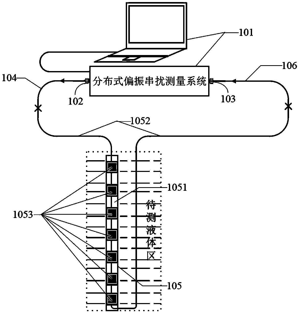
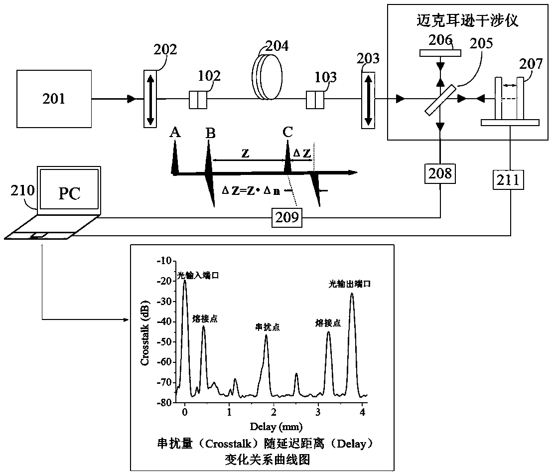
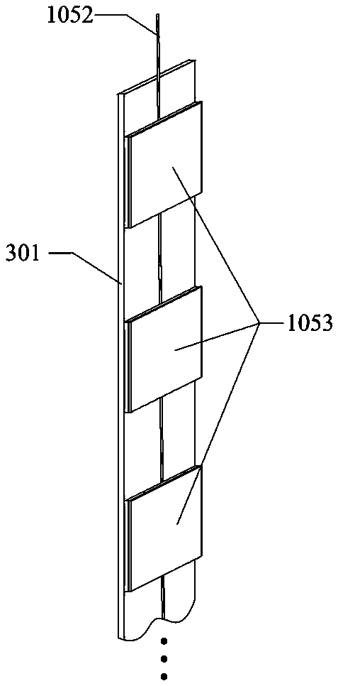
The invention provides a hydraulic optical fiber sensing system and a manufacturing method of the inner sensing baseband of the hydraulic optical fiber sensing system. The hydraulic optical fiber sensing system includes a distributed polarization crosstalk measurement system, a sensing baseband, and an input and output polarization-maintaining optical fiber patch cable; the sensing baseband includes a supporting baseband, a sensing polarization-maintaining optical fiber and pressure applying units; the pressure applying units are used for applying pressure to the sensing polarization-maintaining optical fiber in liquid and are also used for fixing the sensing polarization-maintaining optical fiber onto the supporting baseband; and the pressure applying units as well as the sensing polarization-maintaining optical fiber and the supporting baseband form a sensing unit. According to the hydraulic optical fiber sensing system of the invention, a relationship between polarization crosstalkintensity and the pressure or depth of the liquid can be established, and the pressure intensity, depth, and stratification position of the liquid can be measured. With the hydraulic optical fiber sensing system of the invention adopted, high-spatial resolution and wide-depth range quasi-distribution type measurement can be realized. The hydraulic optical fiber sensing system and the manufacturingmethod of the invention have a potential application value in large-scale liquid storage facility monitoring, water level monitoring, liquid depth or liquid detection and other engineering fields.

Description

technical field [0001] The invention relates to the technical field of optical fiber sensing, in particular to a hydraulic optical fiber sensing system and a method for making its inner sensing baseband. Background technique [0002] Polarization-maintaining fiber (also known as polarization-maintaining fiber) is a special kind of fiber that artificially introduces high birefringence, usually by adding a stress zone in the fiber cladding, so that the fiber core has different The refractive index of , where the high refractive index is called the slow axis, and the low refractive index is called the fast axis, the polarization state of the linearly polarized light waves (or polarization modes) transmitted along two orthogonal directions in the fiber can be maintained during transmission constant. However, under the action of factors such as external pressure, energy coupling will occur between the two orthogonal polarization modes of the PM fiber at the location of the event...

Claims


Application Information

Patent Timeline
IPC IPC(8): G01L11/02G01F23/292
CPCG01F23/292G01L11/02
Inventor 冯亭张泽恒丁东亮姚晓天
Owner HEBEI UNIVERSITY
Learn More