A large-field-of-view high-resolution three-dimensional diffraction tomography microscopy imaging method

A technology of microscopic imaging and large field of view, which is applied in the measurement of phase influence characteristics, etc., can solve the problem that high resolution and large field of view cannot be taken into account at the same time, and achieves improved axial resolution and lateral resolution, and high reconstruction resolution. Effect

Active Publication Date: 2020-08-11
NANJING UNIV OF SCI & TECH
View PDF7 Cites 0 Cited by
  • Summary
  • Abstract
  • Description
  • Claims
  • Application Information

AI Technical Summary

Problems solved by technology

[0005] The purpose of the present invention is to provide a large-field-of-view high-resolution three-dimensional Fourier stack diffraction tomography microscopy imaging method based on LED array illumination, which not only requires no interference, simplifies the optical path of the imaging system, but is also highly compatible with traditional bright-field microscopes , by increasing the illumination angle under the low magnification objective lens, the technical problem of traditional three-dimensional refractive index diffraction tomography that high resolution and large field of view cannot be taken into account at the same time is solved

Method used


Image

  • A large-field-of-view high-resolution three-dimensional diffraction tomography microscopy imaging method
  • A large-field-of-view high-resolution three-dimensional diffraction tomography microscopy imaging method
  • A large-field-of-view high-resolution three-dimensional diffraction tomography microscopy imaging method

Examples


Embodiment Construction

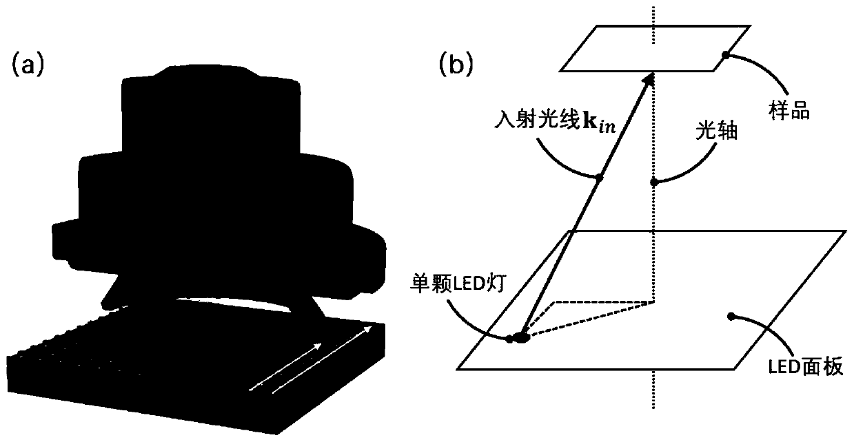
[0020] Such as figure 1 As shown, the illumination source of a conventional brightfield microscope is replaced by a high-density LED array. The LED array is placed on the front focal plane of the condenser, and the rear-end imaging system is consistent with the traditional bright field microscope. Where f is the focal length of the condenser, generally between 10-20mm, and the center of the LED array is on the optical axis of the imaging system. The LED array includes several (at least 261) LED units arranged at equal intervals to form a two-dimensional array. Each LED unit is a red, green and blue three-color LED unit, and its typical wavelengths are red light 633nm, green light 525nm and blue light 465nm. The typical value of the distance d between the centers of each LED unit is 1-4mm. The LED array does not need to be processed separately, and generally can be directly purchased in the market. Table 1 shows the product parameters of a commercially available LED array. ...


PUM


Abstract

The invention discloses a large-visual-field high-resolution three-dimensional Fourier laminated diffraction tomography method based on LED array illumination. Firstly, an original intensity image iscollected, the spatial frequency of incident light corresponding to each LED lamp in an illumination system is calculated according to a coordinate position of each LED of the LED array in a space, and then a large-visual-field high-resolution three-dimensional frequency spectrum of a measured object is initialized; the initialized matrix satisfies the minimum sampling number in each direction andthe final imaging resolution ratio requirements, and the intensity images taken at all illumination angles are iterated to the initialized three-dimensional frequency spectrum, multiple iterating isperformed, a three-dimensional frequency spectrum of the measured object is obtained through iterating, and the three-dimensional frequency spectrum is transformed into a spatial domain; and finally,the large-visual-field high-resolution refractive index information distribution of the measured three-dimensional object is obtained. An objective lens with high amplification factor is not needed, and high reconstruction resolution ratio can be achieved in the premise of ensuring large imaging visual field.

Description

technical field [0001] The invention belongs to optical microscopic measurement and three-dimensional refractive index imaging technology, in particular to a large-field-of-view high-resolution three-dimensional Fourier stack diffraction tomographic microscopic imaging method based on an LED array. Background technique [0002] Most living cells and unstained biological specimens are colorless and transparent, because the refractive index and thickness of each part of the microstructure in the cell are different. When the light wave passes through, the wavelength and amplitude do not change, only the phase This phase difference cannot be observed by the human eye. This requires some chemical or biological means to stain the cells to make them visible under the microscope. Because different substances in biological cells have different absorption rates for colored dyes, the internal structure of biological cells can be seen under the microscope and show different biological ...

Claims


Application Information

Patent Timeline
Patent Type & Authority Patents(China)
IPC IPC(8): G01N21/41
CPCG01N21/41
Inventor 左超李加基陈钱孙佳嵩冯世杰张玉珍顾国华张佳琳范瑶丁君义
Owner NANJING UNIV OF SCI & TECH
Why Eureka
Try Eureka