Test chamber for point source transmittance tests

A point source transmittance, test cavity technology, applied in transmittance measurement and other directions, can solve problems such as inability to deduct, unfavorable stray light test, uncontrollable light path, etc., to achieve high absorption and reduce stray light radiation.

Pending Publication Date: 2018-06-15
XI'AN INST OF OPTICS & FINE MECHANICS - CHINESE ACAD OF SCI
View PDF0 Cites 0 Cited by
  • Summary
  • Abstract
  • Description
  • Claims
  • Application Information

AI Technical Summary

Problems solved by technology

[0005] Commonly used test chambers (darkrooms) are usually cubes or cylinders, and the camera to be tested is placed in it for testing to shield the external ambient light. The inner wall material is usually matte black paint or black cloth. The sealed chambers of these structures The body is easily affected by the secondary reflection of stray light from the outer wall of the camera. At the same time, the surface of black paint or black cloth is close to diffuse reflection, and the light path is uncontrollable. When the stray light test is below a certain threshold, the background noise is random noise, which cannot be deducted, which is not conducive to Low Threshold Stray Light Test

Method used


Image

  • Test chamber for point source transmittance tests
  • Test chamber for point source transmittance tests
  • Test chamber for point source transmittance tests

Examples


Embodiment Construction

[0026] The present invention will be further described below in conjunction with the accompanying drawings and specific embodiments.

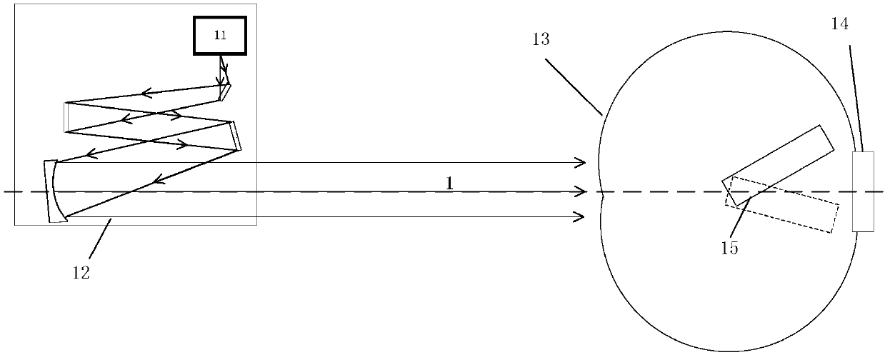
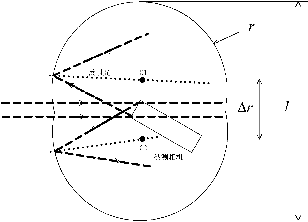
[0027] from figure 2 It can be seen that the test chamber of the present invention includes two symmetrical chambers, the cross section of which constitutes a peanut-like sealed chamber, the inner wall of the sealed chamber is made of a black acrylic plate, and the top and bottom of the sealed chamber are sealed by a flat plate. The cross-sections of the two sealed chambers are all arcs, that is, the side wall of the sealed chamber is formed by the joint of two curved surfaces whose cross-sections are arcs; there is a light entrance at the junction of the two curved surfaces, and the camera to be tested is located on the two curved surfaces. At the midpoint of the line connecting the centers of two circles; the light beam emitted by the collimator enters the camera to be tested through the light entrance; a light trap is set at the opposite jo...


PUM

PropertyMeasurementUnit
Roughnessaaaaaaaaaa

Abstract

The invention belongs to the field of optical system stray light testing, and specifically relates to a test chamber for point source transmittance tests. The test chamber comprises a sealed cavity and a light trap set outside the sealed cavity; the side wall of the sealed cavity comprises two curved surfaces which are in butt joint, the cross sections of the curved surfaces are major arcs, the butt joint position of the curved surfaces is provided with a light inlet; and the top and the bottom of the sealed cavity are sealed by flat plates. The sealed cavity has a structure similar to the structure of a peanut, and an acrylic plate with high absorptivity (superior to 95%) and low scattering rate (less than 1%) is creatively used as an inner wall material for effectively avoiding secondaryreflection light of the outer wall of a camera to enter into the interior of the camera.

Description

technical field [0001] The invention belongs to the field of stray light testing of optical systems, and in particular relates to a testing chamber used for point source transmittance testing of optical systems. Background technique [0002] When the space optical system is in orbit, it is affected by stray light sources such as direct sunlight and diffuse reflection from the earth. Therefore, before it is put into operation, it must be tested on the ground to evaluate its ability to suppress stray light. Pass rate (PST) is a commonly used evaluation index at present. [0003] figure 1 It is the schematic diagram of the light path for the point source transmittance test. When the parallel light beam is incident on the light inlet of the camera, the signal obtained on the camera detection surface is not only the energy after the camera’s own stray light suppression and attenuation (that is, reflecting the measured camera’s own stray light suppression ability, which is also ...

Claims


Application Information

Patent Timeline
IPC IPC(8): G01N21/59
CPCG01N21/59
Inventor 李朝辉赵建科徐亮刘峰李晓辉于敏张玺斌
Owner XI'AN INST OF OPTICS & FINE MECHANICS - CHINESE ACAD OF SCI
Why Eureka
Try Eureka