Flat panel detector and lag data sheet generation method and lag compensation correction method thereof

A flat-panel detector and correction method technology, which is applied in image data processing, instruments, semiconductor devices, etc., can solve problems such as inability to effectively eliminate complex afterimages, and achieve a wide range of applications

Active Publication Date: 2018-06-15
SHANGHAI IRAY TECH
View PDF5 Cites 7 Cited by
  • Summary
  • Abstract
  • Description
  • Claims
  • Application Information

AI Technical Summary

Problems solved by technology

[0006] In view of the shortcomings of the prior art described above, the object of the present invention is to provide a method for generating flat panel detectors and their afterimage data tables, and an afterimage co

Method used


Image

  • Flat panel detector and lag data sheet generation method and lag compensation correction method thereof
  • Flat panel detector and lag data sheet generation method and lag compensation correction method thereof
  • Flat panel detector and lag data sheet generation method and lag compensation correction method thereof

Examples


Embodiment 1

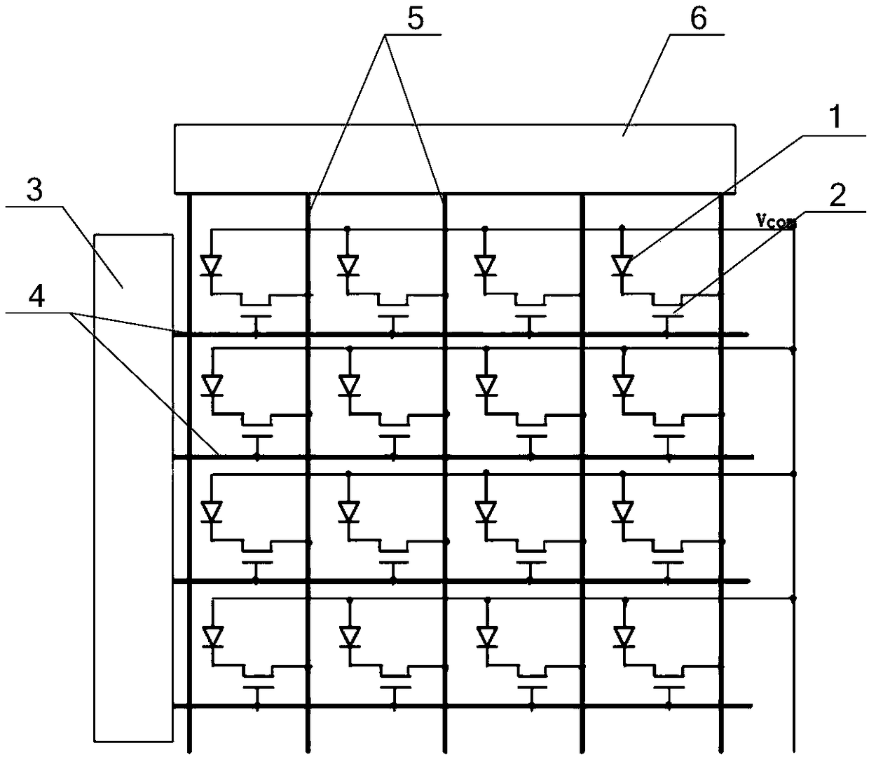
[0046] see Figure 5 , the present invention provides a method for generating an afterimage data table, the steps at least include the following:

[0047] S1. Acquire n dark field images without X-ray exposure, where n≥4, and n is a positive integer;

[0048] S2. Adding and averaging the dark field images to obtain a dark field correction template, which is used to correct the background dark current noise of the image;

[0049] S3. Expose the flat panel detector at a set dose, and collect the current signal, wherein the set dose satisfies the condition: make both the readout circuit and the photodiode of the flat panel detector reach a saturated state;

[0050] S4. Select multiple time points t 1 , t 2 ,...t n The dark field images are collected separately, where the dark field images are correspondingly expressed as: D t1 ,D t2 ,…D tn ;

[0051] S5. Calculate the afterimage value, satisfying the condition: lag tn =D tn -offset, where lag tn for t n The afterimage...

Embodiment 2

[0056] see Figure 6 , the present invention also provides a method for compensating and correcting image sticking of a flat panel detector, the method for compensating and correcting image sticking at least includes the following steps:

[0057] S1', generate afterimage data table, and store in flat panel detector or detector software;

[0058] S2', acquiring the current bright field image and dark field image;

[0059] S3'. Correspond the afterimage signal of each pixel in the dark field image with the afterimage data table, find out the corresponding afterimage value of the afterimage signal of each pixel in the afterimage data table and the corresponding afterimage value moment;

[0060] S4', taking the moment corresponding to the afterimage value plus the time interval between the acquisition of the current bright-field image and the dark-field image as a new moment, and finding the afterimage value corresponding to the new moment in the afterimage data table, Generate...

Embodiment 3

[0070] see Figure 8 , the difference between this embodiment and Embodiment 2 is that the steps of obtaining the current bright field image and dark field image at least include the following:

[0071] S21", collecting a dark field image, wherein the dark field image contains a signal remaining from previous exposure, and the time for collecting the dark field image is any moment between the current exposure and the immediately preceding exposure;

[0072] S22", flat panel detector exposure;

[0073] S23", collecting a bright-field image, wherein the bright-field image includes a current exposure signal and a residual signal from a previous exposure.

[0074] It should be noted that in this embodiment, since the bright field image is collected after the dark field image, when querying the position corresponding to the afterimage signal of each pixel in the dark field image and the afterimage data table, The way to look up the table is to search from the front end to the bac...


PUM


Abstract

The invention provides a compensation correction method of a flat panel detector image lag. The compensation correction method comprises the following steps of generating a lag data sheet and storingthe data sheet in a flat panel detector or detector software; obtaining a current bright field image and a dark filed image; enabling a lag signal of each pixel in the dark field image to be corresponding to the lag data sheet, and finding out a lag value of the lag signal of each pixel corresponding to the lag data sheet, and a moment corresponding to the lag value; enabling the moment corresponding to the lag value to be added with the time interval of the collection time between the current bright field image and the dark field image to obtain a new moment, finding a lag value correspondingto the new moment from the lag data sheet, and generating a current image evaluation lag template matrix; and enabling the lag template matrix to be subtracted from the current bright field image toperform lag compensation correction. The compensation correction method of the flat panel detector image lag disclosed in the invention can be used for solving the complex lag problems, and is wide inapplicable range, and suitable for a noncrystalline silicon detector and amorphous selenium, CMOS and other semiconductor detectors.

Description

technical field [0001] The present invention relates to the technical field of X-ray flat panel detectors, in particular to a method for generating a flat panel detector and its afterimage data table, and an afterimage compensation and correction method. Background technique [0002] The detector is an imaging device for radiographic imaging, and its structure is composed of a scintillator, a thin-film transistor (TFT) photosensitive panel, a signal reading and transmission circuit, and a mechanical structure. At present, it is mainly used in clinical radiological diagnostic imaging. The imaging principle of the flat panel detector: X-rays pass through the object to be inspected and are incident on the surface of the detector. The scintillator converts the X-rays into visible light, and the TFT photosensitive array absorbs the visible light and converts it into photoelectric charges. The photoelectric charge is converted into a level signal, which is converted into a digita...

Claims


Application Information

Patent Timeline
IPC IPC(8): H01L31/08H01L31/18G06T5/00
CPCG06T5/00H01L31/085H01L31/18Y02P70/50
Inventor 黄细平王锋张楠金利波
Owner SHANGHAI IRAY TECH
Why Eureka
Try Eureka