Ultraviolet detection converter and methods for preparing and using same

A converter, ultraviolet technology, applied in instruments, semiconductor devices, optics, etc., can solve the problems of high cost and difficult development of readout circuits, and achieve the effect of prolonging service life, low price, and cheap ultraviolet detection

Active Publication Date: 2015-10-07
HARBIN INST OF TECH
View PDF3 Cites 5 Cited by
  • Summary
  • Abstract
  • Description
  • Claims
  • Application Information

AI Technical Summary

Problems solved by technology

[0003] The present invention aims to solve the technical problems of high technical difficulty and high cost in the development of the readout circuit of the existing ultraviolet detector, and provides an ultraviolet detection converter and its preparation and use method

Method used


Image

  • Ultraviolet detection converter and methods for preparing and using same
  • Ultraviolet detection converter and methods for preparing and using same
  • Ultraviolet detection converter and methods for preparing and using same

Examples


specific Embodiment approach 1

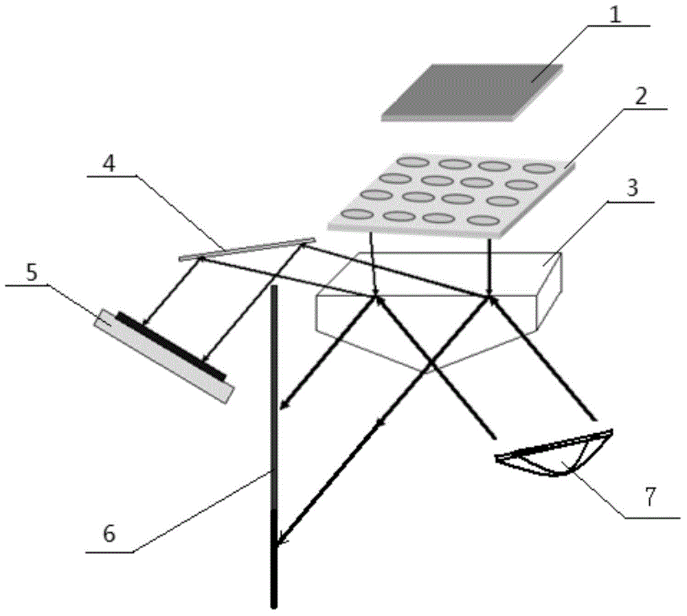
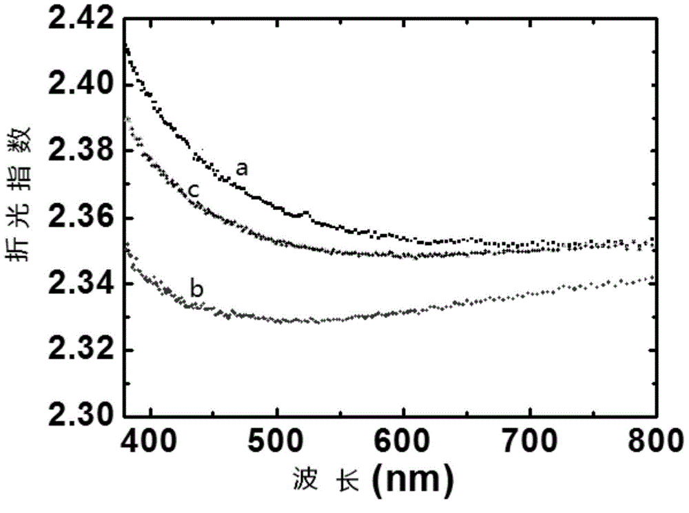
[0023] Embodiment 1: The ultraviolet detection converter of this embodiment is an optical isosceles prism cut from a transparent relaxor ferroelectric ceramic material, wherein the apex angle of the isosceles triangle in the cross section of the prism is 150° to 165°, and the relaxation The bandgap width Eg of the Henan ferroelectric ceramic material is 3.0-4.0eV, the Curie temperature is 10-60°C, and the value of the decrease in the refractive index caused by ultraviolet radiation is ≥0.02.

specific Embodiment approach 2

[0024] Embodiment 2: The difference between this embodiment and Embodiment 1 is that the relaxor ferroelectric ceramic material is lead lanthanum zirconium titanium ytterbium niobate (Pb 0.90 La 0.10 [(Yb 1 / 2 Nb 1 / 2 ) 0.15 (Zr 0.425 Ti 0.575 ) 0.85 ] 0.975 o 3 ), or the relaxor ferroelectric ceramic material is lead lanthanum zirconate titanate (Pb 1-x La x )(Zr y Ti 1-y ) 1-x / 4 o 3 , PLZT), where x=0.1, y=0.65; or the relaxation ferroelectric ceramic material PbMg 1 / 3 Nb 2 / 3 o 3 The mass percentage is 71%, lead titanate (PbTiO 3 ) with a mass percentage of 29% of the formed PbMg 1 / 3 Nb 2 / 3 o 3 with PbTiO 3 of solid solution. Others are the same as the first embodiment.

specific Embodiment approach 3

[0025] Specific embodiment three: the difference between this embodiment and embodiment one or two is that the two symmetrical isosceles prism surfaces of the isosceles triangular prism are vapor-deposited or deposited multi-layer dielectric film, and the multi-layer dielectric film has a central wavelength of 800nm ​​light. High transmittance; others are the same as those in Embodiment 1 or 2. Of which SiO 2 with TiO 2 A multilayer film with an alternating periodic structure, the film thickness is λ / 4, and λ is a central wavelength of 800nm. The preparation of this multilayer dielectric antireflection film is a conventional film preparation method.


PUM

PropertyMeasurementUnit
angleaaaaaaaaaa
Curie pointaaaaaaaaaa
thicknessaaaaaaaaaa

Abstract

The invention relates to an ultraviolet detection converter and methods for preparing and using same, and relates to an ultraviolet detection and imaging method. The invention aims to solve the problems that a reading circuit of a present ultraviolet detector is difficult in technology and high in cost. An ultraviolet detection converter is an optical isosceles prism formed by cutting transparent relaxor ferroelectric ceramic material, and the vertex angle of an isosceles triangle is 150 to 165 degrees. The method for preparing the ultraviolet detection converter comprises cutting a relaxor ferroelectric ceramic block into an isosceles prism, grinding and polishing to obtain the ultraviolet detection converter. Ultraviolet light emitted from an ultraviolet lens array irradiates on the bottom of the ultraviolet detection converter, near infrared parallel light emitted from an infrared light source irradiates on the bottom of the ultraviolet detection converter in the way that incident angle is less than a total internal reflection angle, and a silicon detector array receives the light. The spatial distribution of the near infrared light is the same as that of the ultraviolet light emitted from the ultraviolet lens array, a reading circuit and array processing are needless.

Description

technical field [0001] The invention relates to a method for ultraviolet detection and imaging. Background technique [0002] The development of ultraviolet (UV) photodetectors has attracted extensive attention due to the increasing demands in the fields of industry, environment, and biology. In the development of ultraviolet photodetectors, a new generation of wide-bandgap semiconductor materials, such as (Al,In)GaN, diamond and SiC, have shown advantages. On the other hand, one-dimensional (1D) semiconductor nanostructures with wide band gaps are also considered as candidate materials for the development of high-efficiency UV photodetectors, such as ZnO nanowires, gallium oxide nanowires, nanoflakes, GaN Significant improvements in optical sensitivity have been observed in nanowires or other metal oxide nanostructures. However, in the development of these ultraviolet detectors, the readout circuit is indispensable. To meet the imaging requirements, it is necessary to exp...

Claims


Application Information

Patent Timeline
Patent Type & Authority Applications(China)
IPC IPC(8): G02F1/05G02B5/04H01L31/101
CPCG02B5/04G02F1/05H01L31/101
Inventor 赵华张景文
Owner HARBIN INST OF TECH
Why Eureka
Try Eureka