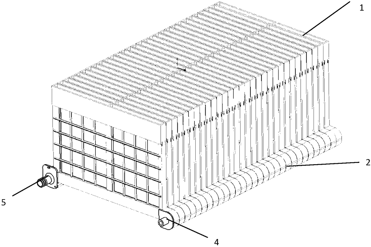
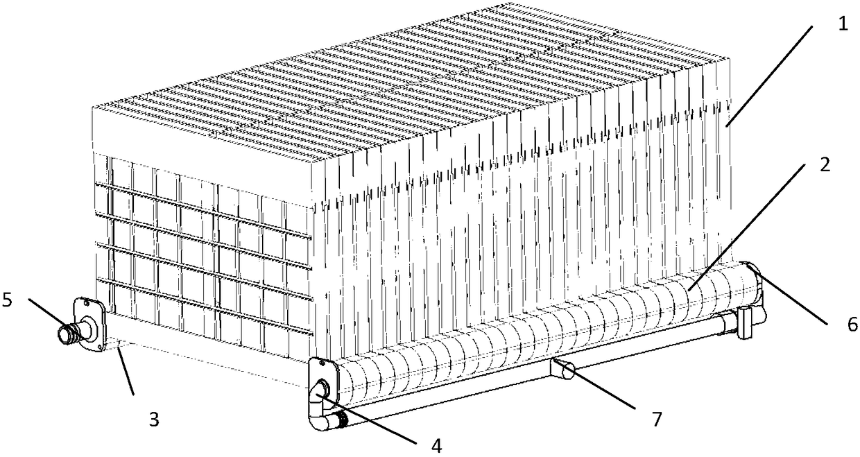
Metal/air battery system
An air battery and air battery stack technology, applied in fuel cells, fuel cell additives, circuits, etc., can solve the problems of insufficient heat dissipation, the volume occupied by the main circuit, and the branch circuit cannot be too thin, so as to improve the anode utilization rate, The effect of improving flow consistency and increasing discharge capacity
- Summary
- Abstract
- Description
- Claims
- Application Information
AI Technical Summary
Problems solved by technology
Method used
Image
Examples
Embodiment 1
[0039] The structure of the battery pack is the same as in Example 1, but only one main liquid injection port and one main liquid discharge port are used in this embodiment, and a flow equalization unit is built in the main liquid injection channel, and the flow equalization unit is a separator structure , set along the direction of fluid flow, the width of the separator is 30 mm in diameter of the main liquid injection pipe, and the length is 600 mm, which is the same as the length of the main channel, and one end (9) of the separator is glued to the end of the main liquid injection port A (4) , divide the electrolyte injected into the middle of the main channel evenly into two parts, one part starts from the main liquid injection port A and directly injects into each single cell of the battery pack along the single cell liquid injection port, and the other part is divided by the injection part far away from the single cell side. The liquid flow channel brings the electrolyte ...
Embodiment 2
[0043] The structure of the battery pack is the same as that in Example 1, but in this example, a wedge-shaped partition is added in the main liquid injection channel. The cross-sectional shape of the partition is a right-angled triangle, and the length of the long side of the right-angled side is 600mm for the main liquid injection channel. , the length of the short side of the right-angled side is 4 / 5, and the diameter of the main liquid injection channel is 24mm. , is 15mm thick. When the electrolyte is injected into the side of the main liquid injection port A and flows through the triangular separator, the cross-sectional area of the main channel gradually decreases, so that the static pressure at the entrance of each single cell is equal, and the electrolyte can be injected into the single cell more uniformly. The main liquid injection port B The A side is sealed by the end plate, and only the A side can be filled with liquid. Liquid injection was performed at 9L / min,...
Embodiment 3
[0047] The structure of the battery pack is the same as in Example 1, but in this example, a progressively increasing array of raised partitions is added to the main liquid injection channel. The length of the partition is 600mm for the main liquid injection channel, and the width is 4 / 5 The diameter of the flow channel is 24mm, and the distance between the stepped protrusions is 20mm from the liquid injection port of the single battery. Starting from the side A of the main liquid injection port, the left side of each stepped protrusion is located on the right side of the liquid injection port of the single battery. The height of the long side is 2 / 3 of the diameter of the main liquid injection channel, 20mm, and the stepped slope is that the side of the hypotenuse corresponds to the side of the single battery liquid injection port on the main channel. When the electrolyte is injected into the A side of the main liquid injection port and flows through the stepped separator, the...
PUM
 Abstract
Description
Claims
Application Information
 - R&D
- Intellectual Property
- Life Sciences
- Materials
- Tech Scout
- Unparalleled Data Quality
- Higher Quality Content
- 60% Fewer Hallucinations
Browse by: Latest US Patents, China's latest patents, Technical Efficacy Thesaurus, Application Domain, Technology Topic, Popular Technical Reports.
© 2025 PatSnap. All rights reserved.Legal|Privacy policy|Modern Slavery Act Transparency Statement|Sitemap|About US| Contact US: help@patsnap.com


