Microstructured hollow-core optical fiber

A technology of hollow-core fiber and microstructure, applied in the direction of microstructure fiber, cladding fiber, light guide, etc., can solve the problems that affect the low-loss bandwidth and loss of the fiber, and cannot reduce the limit loss of the fiber, so as to increase the damage threshold and reduce material absorption. Loss, reduce the effect of limiting loss

Active Publication Date: 2018-06-19
JIANGXI NORMAL UNIV
View PDF6 Cites 22 Cited by
  • Summary
  • Abstract
  • Description
  • Claims
  • Application Information

AI Technical Summary

Problems solved by technology

However, for anti-resonant hollow-core fibers with negative curvature, it is not possible to reduce the confinement loss of the fiber by simply adding more ring layers like hollow-core photonic bandgap fibers, because the connection structure between the ring layers causes more damage. The existence of multiple cladding modes affects the low-loss bandwidth and loss reduction of the fiber [S. Février, et al. “Understanding origin of loss in large pitch hollow-corephotonic crystal fibers and their design simplification,” Opt. Express, 2010 ,18(5), 5142-5150]

Method used


Image

  • Microstructured hollow-core optical fiber
  • Microstructured hollow-core optical fiber
  • Microstructured hollow-core optical fiber

Examples


Embodiment 1

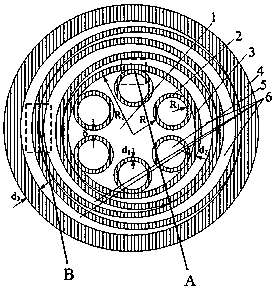
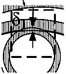
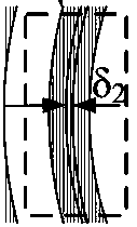
[0028] The invention provides a microstructure hollow fiber, such as figure 1 , figure 2 and image 3 As shown, the optical fiber includes a first-type medium tube 2, a second-type medium tube 3 and a third-type medium tube 4, and the first-type medium tube 2 is nested in the second-type medium tube The inside of the tube 3 is arranged periodically along the circumferential line, the minimum distance δ between the outer walls of two adjacent first-type medium tubes 2 > 0, and the second-type medium tube 3 is nested in the third-type medium tube 4. Inside; the first type of medium tube 2 and the second type of medium tube 3 are connected in a tangential manner, the thickness δ of the intersection of the first type of medium tube 2 and the second type of medium tube 3 1 =0, two adjacent second-type medium tubes 3 are connected in a tangential manner, and the intersecting thickness δ between adjacent second-type medium tubes 3 2 =0, the second-type medium pipe 3 and the third...

Embodiment 2

[0032] The present invention provides a microstructured hollow fiber. The optical fiber includes a first-type medium tube 2, a second-type medium tube 3 and a third-type medium tube 4. The first-type medium tube 2 is nested Inside the second-type medium tubes 3 and arranged periodically along the circumference, the minimum distance between the outer walls of two adjacent first-type medium tubes 2 is greater than 0, and the second-type medium tubes 3 are nested in The inside of the third type of medium tube 4; the first type of medium tube 2 and the second type of medium tube 3 are connected in an intersecting manner, the first type of medium tube 2 and the second type of medium Thickness δ of circular tube 3 intersecting 1 >0, two adjacent second-type medium circular tubes 3 are connected by intersection, the thickness δ of the intersection between adjacent second-type medium circular tubes 3 2 >0, the round pipe 3 of the second type of medium and the round pipe 4 of the thir...

Embodiment 3

[0035] The present invention provides a microstructured hollow fiber. The optical fiber includes a first-type medium tube 2, a second-type medium tube 3 and a third-type medium tube 4. The first-type medium tube 2 is nested Inside the second-type medium tubes 3 and arranged periodically along the circumference, the minimum distance between the outer walls of two adjacent first-type medium tubes 2 is greater than 0, and the second-type medium tubes 3 are nested in The inside of the third type of medium tube 4; the first type of medium tube 2 and the second type of medium tube 3 are connected in a tangential manner, the first type of medium tube 2 and the second type of medium tube The intersecting thickness δ of medium pipe 3 1 =0, two adjacent second-type medium tubes 3 are connected by intersection, the thickness δ of the intersection between adjacent second-type medium tubes 3 2 >0, the second-type medium pipe 3 and the third-type medium pipe 4 are connected in a tangential...


PUM


Abstract

The present invention provides a microstructured hollow-core optical fiber. The optical fiber comprises first type medium circular tubes, second type medium circular tubes, and a third type medium circular tube; the first type medium tubes are nested in the second type medium circular tubes and are periodically distributed along the circumference of the second type medium circular tubes; intervalsbetween the outer walls of the adjacent first type medium circular tubes are greater than 0; the second type medium circular tubes are nested in the third type medium circular tube; and the first type medium circular tubes, the second type medium circular tubes and the third type medium circular tube are connected with one another in a tangent or intersecting manner. According to the microstructured hollow-core optical fiber of the invention, confinement loss can be lowered by simply increasing the number of the second type medium circular tubes, so that a difficulty that the confinement lossof a negative-curvature anti-resonant hollow-core optical fiber cannot be reduced by simply adopting a means of increasing annular layers which assists in reducing the confinement loss of a hollow-core photonic band gap optical fiber can be eliminated. According to the optical fiber provided by the invention, too many nodes will not be introduced into the cross section of the optical fiber, and anew scheme and idea can be provided for the design and manufacture of a broadband low-loss hollow-core optical fiber.

Description

technical field [0001] The invention relates to the field of optical fiber communication, in particular to a microstructure hollow fiber. Background technique [0002] Hollow-core optical fiber can achieve more than 99% of light propagating in the air, and only a very small amount of light in the material, which greatly reduces the influence of optical fiber material characteristics on optical signal quality and optical fiber performance, thereby greatly improving network speed and transmission bandwidth. Transmission distance. [0003] Anti-resonant hollow-core fiber is a type of hollow-core fiber, F. Benabid et al. [F. Benabid, et al. "Stimulated Raman scattering in hydrogen-filled hollow-core photoniccrystal fiber," Science, 2002, 298(5592), 399 -402] proposed a hollow-core microstructured fiber with a Kagome cladding structure, which is similar to the hollow-core photonic bandgap fiber, but the periodicity is not so strict, which reduces the difficulty of fiber fabricat...

Claims


Application Information

Patent Timeline
Patent Type & Authority Applications(China)
IPC IPC(8): G02B6/032G02B6/02
CPCG02B6/02295G02B6/032Y02P40/57
Inventor 祝远锋饶春芳张莹邹光涛罗海梅
Owner JIANGXI NORMAL UNIV
Why Eureka
Try Eureka