
Optimum design method of dynamic performance of aero-engine fastening junction surface

An aero-engine and dynamic performance technology, applied in design optimization/simulation, calculation, special data processing applications, etc., can solve problems such as long design cycle, irregular shape, and impact of aero-engines

Active Publication Date: 2018-06-22
XI AN JIAOTONG UNIV
View PDF5 Cites 2 Cited by
  • Summary
  • Abstract
  • Description
  • Claims
  • Application Information

AI Technical Summary

Problems solved by technology

[0002] Aeroengine is a kind of highly complex precision machinery, and bolt connection is widely used in it, which directly affects the performance, reliability and economy of the aircraft; in order to improve the dynamic performance, in the traditional active design, the designer establishes a dynamic model Carry out dynamic characteristic analysis, and carry out structural modification and optimization design according to dynamic design indicators. However, in recent years, due to the continuous development of aero-engines in the direction of high speed and high thrust-to-weight ratio, such a design method will inevitably lead to long aero-engine design cycles and optimization. In order to solve this problem, researchers at home and abroad often use some topology optimization methods such as homogenization method and variable density method to actively optimize the design of the fastening joint surface, but this Class methods generally have problems such as fuzzy design boundaries and irregular shapes, which greatly reduce the machinability and practicability of the design results;

Method used


Image

  • Optimum design method of dynamic performance of aero-engine fastening junction surface
  • Optimum design method of dynamic performance of aero-engine fastening junction surface
  • Optimum design method of dynamic performance of aero-engine fastening junction surface

Examples


Embodiment Construction

[0068] Below in conjunction with accompanying drawing and embodiment this method is described in detail;

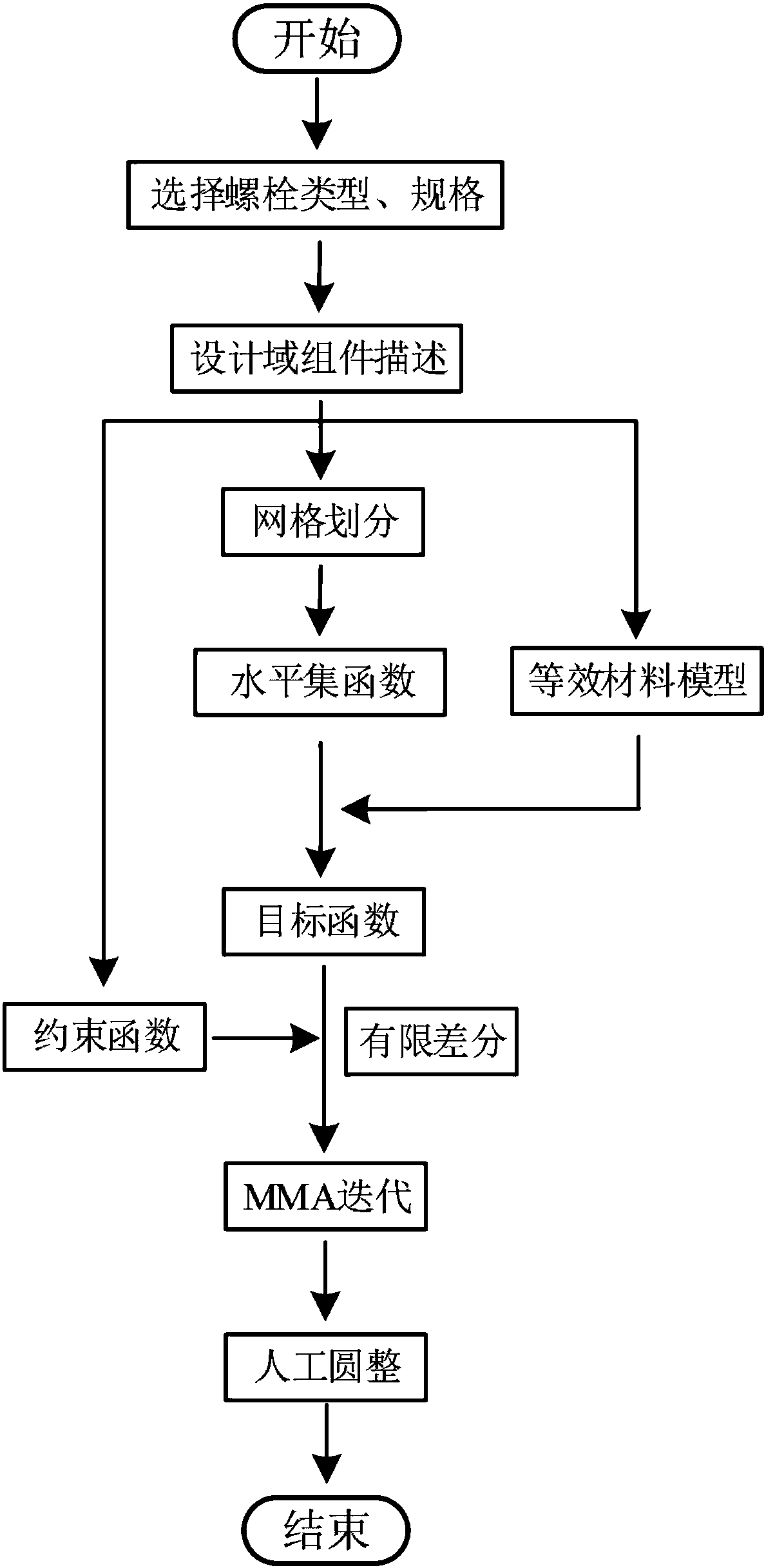
[0069] Such as figure 1 As shown, an optimal design method for the dynamic performance of the fastened joint surface of an aero-engine includes the following steps:

[0070] 1) According to the needs of the actual assembly of the aero-engine, determine the type, specification, assembly process and machining accuracy of the bolts used;

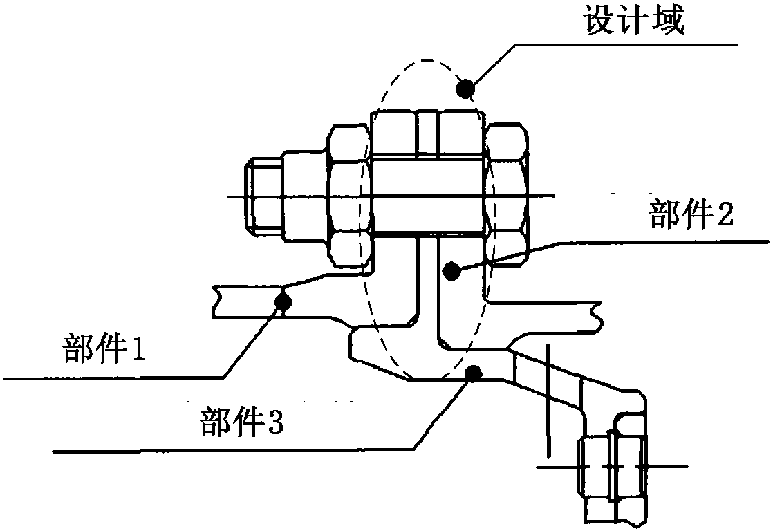
[0071] 2) if figure 2 As shown in the figure, the fastening surface of parts 1, 2 and 3 in the aero-engine is selected as the design domain D, which is described by rectangular components; five design variables are set for each rectangular component, which are: the coordinates of the center point of the rectangle x 0 、y 0 , the length L and width T of the rectangular component, the inclination angle θ of the rectangular component;

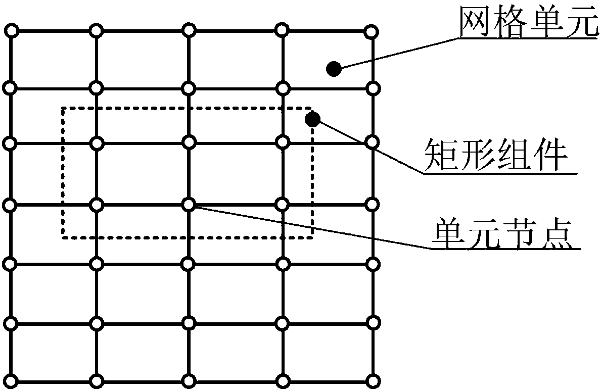
[0072] 3) By using several small four-node quadrilateral grids to divide the design domain, a total of ...


PUM


Abstract

The invention discloses an optimum design method of the dynamic performance of an aero-engine fastening junction surface. The optimum design method comprises the steps of firstly, determining the type, the specification, the assembly technology and the machining precision of adopted bolts; then selecting the aero-engine part fastening junction surface as a design domain, and using a rectangular assembly for description; then adopting several small four-node quadrilateral meshes to divide the design domain, then constructing a rectangular level set function, equalizing the design domain into amaterial model to obtain a unit equivalent rigidity matrix, assembling the equivalent rigidity matrix, and extracting a mass matrix of parts to obtain a kinetic equation and then a target function; then constraining center coordinates of the assembly in the design domain, then conducting iterative optimization, and finally, conducting rounding processing to thus obtain the junction surface joint form with the optimal dynamic performance. By means of the optimum design method of the dynamic performance of the aero-engine fastening junction surface, through optimal design of the junction surface, the optimal solution of the relevant dynamic performance is solved, and a clear design boundary is obtained.

Description

technical field [0001] The method belongs to the technical field of aero-engine design, and specifically relates to an optimal design method for the dynamic performance of an aero-engine fastening joint surface. technical background [0002] Aeroengine is a kind of highly complex precision machinery, and bolt connection is widely used in it, which directly affects the performance, reliability and economy of the aircraft; in order to improve the dynamic performance, in the traditional active design, the designer establishes a dynamic model Carry out dynamic characteristic analysis, and carry out structural modification and optimization design according to dynamic design indicators. However, in recent years, due to the continuous development of aero-engines in the direction of high speed and high thrust-to-weight ratio, such a design method will inevitably lead to long aero-engine design cycles and optimization. In order to solve this problem, researchers at home and abroad of...

Claims


Application Information

Patent Timeline
Patent Type & Authority Applications(China)
IPC IPC(8): G06F17/50
CPCG06F30/15G06F30/17G06F30/23
Inventor 李宝童洪军黄从甲朱林波郭俊康
Owner XI AN JIAOTONG UNIV
Learn More