
Electronic product production equipment

A technology for production equipment and electronic products, applied in circuits, electrical components, electric solid devices, etc., can solve the problems of high friction on the surface of the protective film, easy scratching of the protective film, and exposure of IC patterns, etc., to achieve a good patch effect , good grinding effect, and the effect of reducing friction

Active Publication Date: 2020-06-02
山东贝斯特信息科技有限公司
View PDF6 Cites 0 Cited by
  • Summary
  • Abstract
  • Description
  • Claims
  • Application Information

AI Technical Summary

Problems solved by technology

[0005] However, in the existing wafer placement equipment, the following problems often occur: during the placement process, the protective film is often pasted on the front of the wafer by sliding friction. This method of placement makes the friction force on the surface of the protective film Larger, the protective film is easily scratched, resulting in the process of grinding the wafer with the front side down, the IC pattern on the wafer surface is easily exposed from the protective film and damaged, resulting in the failure of the wafer and improving the quality of the wafer. round defect rate

Method used


Image

  • Electronic product production equipment
  • Electronic product production equipment

Examples


Embodiment Construction

[0019] Further detailed explanation through specific implementation mode below:

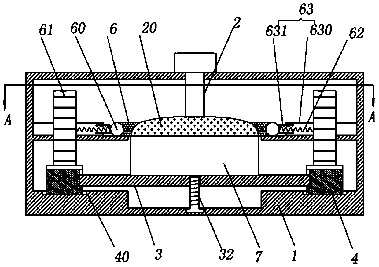
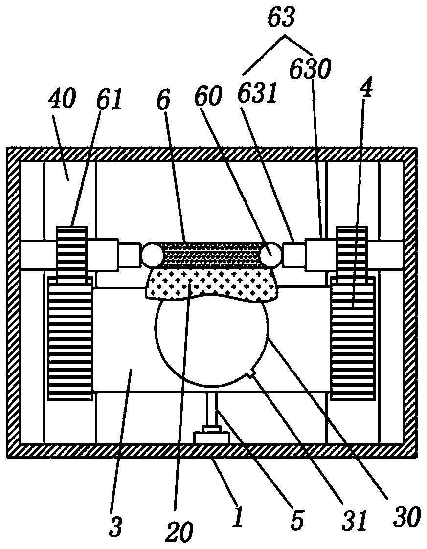
[0020] The reference signs in the drawings of the description include: frame 1, patch mechanism 2, protective film 20, support plate 3, groove 30, notch 31, lifting screw 32, sliding rack 4, axial chute 40, moving Pneumatic cylinder 5, flattening air bag 6, steel ball 60, rolling gear 61, tension spring 62, telescopic tube 63, outer tube 630, inner sliding tube 631, wafer 7.

[0021] The embodiment is basically as attached figure 1 Shown:

[0022] The electronic product production equipment includes a frame 1, a placement mechanism 2, a moving mechanism and a flattening mechanism. Wherein, the placement mechanism 2 may adopt a structure in the prior art, that is, a structure capable of pulling the protective film 20 to the surface of the wafer 7 and performing subsequent cutting. Such as figure 2 As shown, the moving mechanism includes a support plate 3, a sliding rack 4, and a mover for tra...


PUM


Abstract

The invention belongs to the technical field of production of electronic products, and specifically relates to electronic product production equipment. The electronic product production equipment includes a rack, and also includes a movement mechanism and a flattening mechanism; the movement mechanism includes a support plate, sliding racks and a mover used for enabling translation of the supportplate; a fixing part used for fixing a wafer is arranged on the support plate, and two ends of the support plate are each connected with a sliding rack; the sliding racks are slidably connected with the rack; the flattening mechanism includes a flattening airbag and rolling units symmetrically arranged at two ends of the flattening airbag; each rolling unit includes a rolling ball, a rolling gearand a rigid connecting part; the rolling ball is fixedly connected with the flattening airbag; the rolling gear meshes with the sliding racks, and is rotatably connected with the rack; one end of therigid connecting part is connected with the rolling ball, and the other end of the rigid connecting part is connected with the rolling gear. By adoption of the scheme, a protective film can be effectively prevented from being damaged in a chip mounting process, and the reject ratio of wafers is reduced.

Description

technical field [0001] The invention belongs to the technical field of electronic product production, and in particular relates to electronic product production equipment. Background technique [0002] Electronic products refer to electronic products used in daily consumer life. It is a specific household appliance that contains electronic components and is usually used for entertainment, communication, and clerical purposes, such as telephones, audio equipment, televisions, DVD players, and even electronic clocks. Chips, also known as microcircuits, microchips, and integrated circuits, refer to silicon chips containing integrated circuits. They are small in size and are the most important part of electronic products, undertaking the functions of computing and storage. The complete process of chip production includes several links such as chip design, wafer production, packaging production, and cost testing; the raw material for its production is wafers. Wafer refers to th...

Claims


Application Information

Patent Timeline
Patent Type & Authority Patents(China)
IPC IPC(8): H01L21/683H01L21/67
CPCH01L21/67253H01L21/6836H01L2221/68327
Inventor 廖洪清
Owner 山东贝斯特信息科技有限公司
Learn More