Ultrasound signal processing device, ultrasound signal processing method, and ultrasound diagnostic device

A signal processing device and ultrasonic technology, which are applied in ultrasonic/sonic/infrasonic diagnosis, structure of ultrasonic/sonic/infrasonic diagnosis equipment, and sonic diagnosis, etc. The problem of poor ultrasonic utilization efficiency, etc., achieves the effect of reducing the amount of calculation and the number of

Active Publication Date: 2018-06-29
KONICA MINOLTA INC
View PDF7 Cites 2 Cited by
  • Summary
  • Abstract
  • Description
  • Claims
  • Application Information

AI Technical Summary

Problems solved by technology

Therefore, in an ultrasonic transmission event, only one or a few acoustic line signals (asoustic line signals) on the central axis of the transmitted ultrasonic beam can be generated, and the utilization efficiency of ultrasonic waves is poor.
In addition, when the observation point is far away from the focal point, there is also the problem that the spatial resolution of the obtained sound ray signal and the signal S / N ratio decrease.

Method used


Image

  • Ultrasound signal processing device, ultrasound signal processing method, and ultrasound diagnostic device
  • Ultrasound signal processing device, ultrasound signal processing method, and ultrasound diagnostic device
  • Ultrasound signal processing device, ultrasound signal processing method, and ultrasound diagnostic device

Examples


Embodiment approach 1

[0041]

[0042] Hereinafter, the ultrasonic diagnostic apparatus 100 according to Embodiment 1 will be described with reference to the drawings.

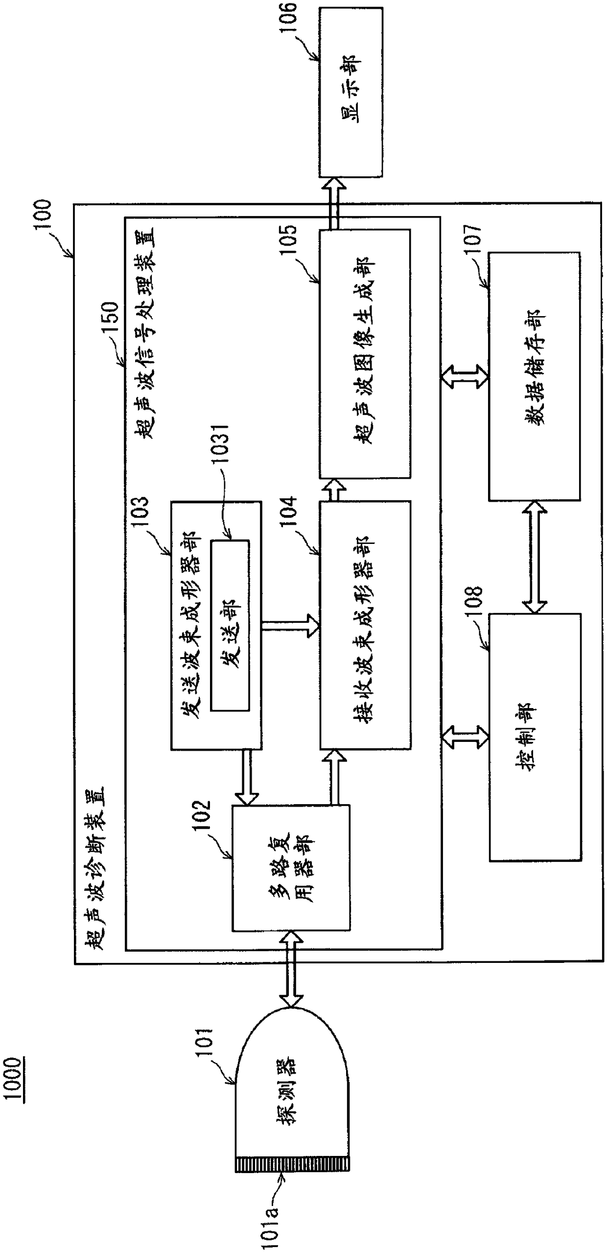
[0043] figure 1 It is a functional block diagram of the ultrasonic diagnostic system 1000 according to the first embodiment. Such as figure 1 As shown, the ultrasonic diagnostic system 1000 has: a probe 101, which has a plurality of vibrators 101a that transmit ultrasonic waves toward the subject and receive their reflected waves; The output signal of 101 generates an ultrasonic image, and the display unit 106 displays the ultrasonic image on the screen. The probe 101 and the display unit 106 are respectively configured to be connectable to the ultrasonic diagnostic apparatus 100 . figure 1 A state in which the probe 101 and the display unit 106 are connected to the ultrasonic diagnostic apparatus 100 is shown. In addition, the probe 101 and the display unit 106 may be located inside the ultrasonic diagnostic apparatus 100 . ...

example 1

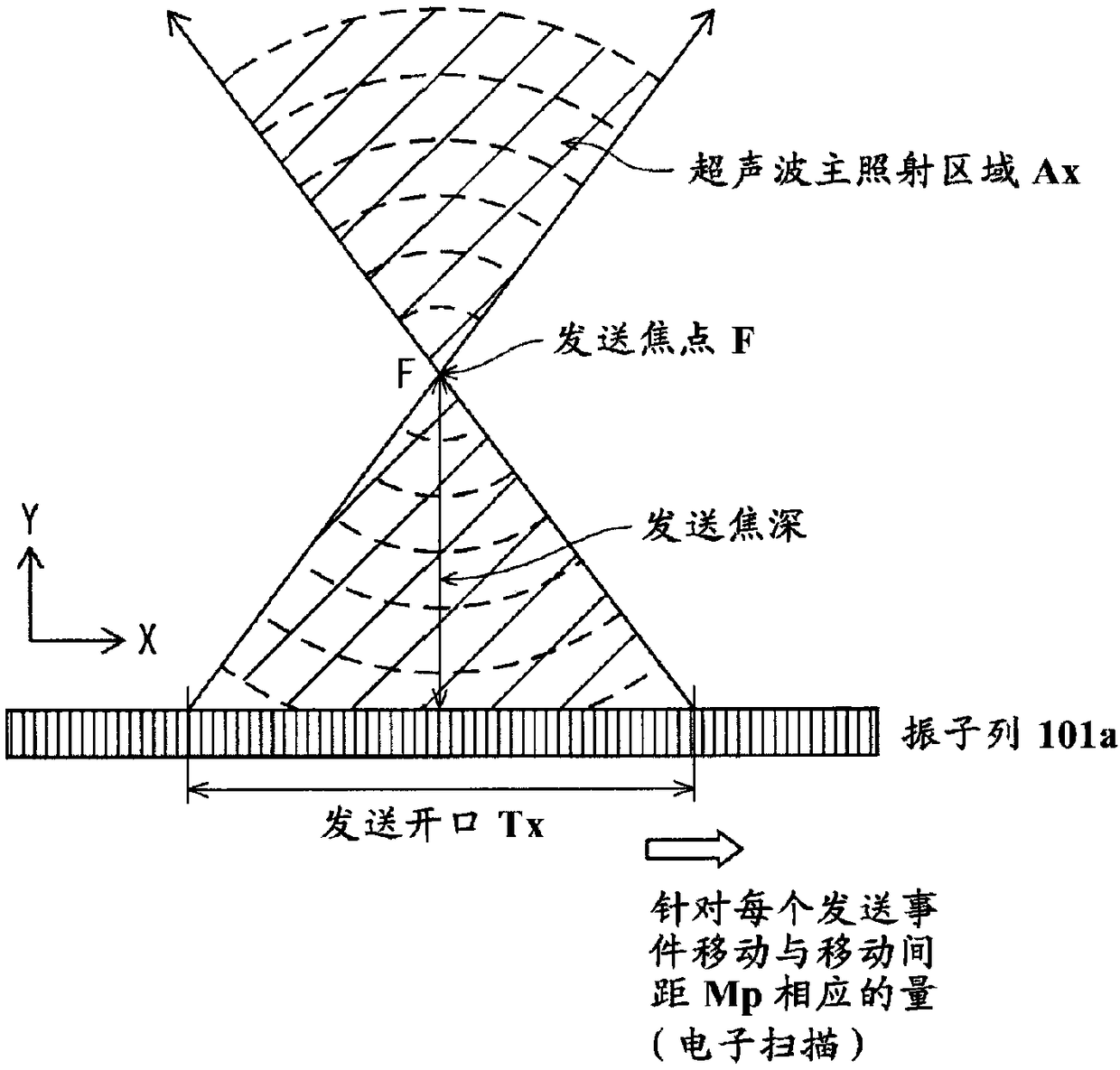
[0148] In the ultrasonic diagnostic apparatus 100 according to Embodiment 1, the receiving aperture setting unit 1043 is configured to select the receiving aperture Rx so as to match the transducer whose column center is spatially closest to the observation point P. However, the reception aperture Rx can be calculated based on the total propagation time until the ultrasonic wave transmitted from the transmission aperture Tx is reflected at the observation point Pij in the target area Bx via the transmission focus F and reaches the reception transducer Rk of the reception aperture Rx. It is only necessary to generate sound ray signals for all observation points Pij in the target area Bx by controlling the delay of the propagation path, so the configuration of the receiving aperture Rx can be appropriately changed.

[0149] Modification 1 differs from Embodiment 1 in that it includes a transmission-synchronous reception aperture setting unit (hereinafter referred to as “Tx recept...

example 2

[0160] In the ultrasonic diagnostic apparatuses of Embodiment 1 and Modification 1, the shape of the second target region Bx2 is narrowed by n times in the column direction relative to the similar shape of the first target region Bx2 (1>n>0). shape. However, the shape of the second object area Bx may be the following patterns other than this.

[0161] Figure 17 A first setting example of the second target area Bx2 of Modification 2 is shown. Such as Figure 17 As shown, the second target area Bx2 is a portion corresponding to the inner side of a rectangle whose base is the transmission opening Tx, among the deeper than focus portions in the ultrasonic main irradiation area Ax. Therefore, when the depth of focus is Df, the shape overlaps with the first target region Bx1 within the range of depth from Df to 2×Df. On the other hand, the region whose depth is deeper than 2×Df is a strip-shaped region whose width in the column direction matches the width of the transmission op...


PUM


Abstract

The invention provides an ultrasound signal processing device that enables reducing delay-and-sum computation amount in a synthetic aperture method utilizing converging-type transmission beam formingwhile suppressing decrease in spatial resolution and S / N ratio, an ultrasound diagnostic device, and an ultrasound diagnostic method. The ultrasound signal processing device includes ultrasound signalprocessing circuitry that operates as: a transmitter that causes an ultrasound probe to transmit ultrasound beams to an ultrasound main irradiation area defined by two straight lines each connectinga focal point and a different end of a transmission transducer element array; a receiver that generates receive signal sequences; a delay-and-sum calculator that sets first and second target areas inthe ultrasound main irradiation area, and performs delay-and-summing of receive signal sequences based on ultrasound reflection from measurement points in the first and second target areas thereby togenerate sub-frame acoustic line signals, the first target area is an entirety of an area located at or shallower than a focal depth, the second target area is part of an area located deeper than thefocal depth; and a synthesizer that synthesizes sub-frame acoustic line signals to generate a frame acoustic line signal.

Description

technical field [0001] The present disclosure relates to an ultrasonic signal processing device and an ultrasonic diagnostic device equipped with the ultrasonic signal processing device, and particularly to a reception beamforming processing method in the ultrasonic signal processing device. Background technique [0002] An ultrasonic diagnostic apparatus transmits ultrasonic waves into a subject through an ultrasonic probe (hereinafter referred to as a "probe"), and receives ultrasonic reflected waves (echoes) generated due to differences in acoustic impedance of subject tissues. Furthermore, an ultrasonic tomographic image showing the structure of the internal tissue of the subject is generated based on the received electric signal, and is displayed on a monitor (hereinafter referred to as a "display unit"). Ultrasonic diagnostic devices are widely used for morphological diagnosis of living bodies because they are less intrusive to the subject and can observe the state of ...

Claims


Application Information

Patent Timeline
Patent Type & Authority Applications(China)
IPC IPC(8): A61B8/14
CPCA61B8/14A61B8/5207A61B8/5269A61B8/44A61B8/4488G01S7/52046G01S15/8915G01S15/8997G10K11/346G01S15/8961
Inventor 渡边泰仁
Owner KONICA MINOLTA INC
Why Eureka
Try Eureka