
Electromagnetic induction type wireless charging vehicle with automatic adjustment function

An automatic adjustment and wireless charging technology, applied in electric vehicles, electric vehicle charging technology, charging stations, etc., can solve problems such as reducing charging efficiency, reducing magnetic flux, and non-perpendicular angles between magnetic lines of force and coils, so as to improve charging efficiency and improve The effect of power generation efficiency and accelerated charging efficiency

Inactive Publication Date: 2018-06-29
NANJING WEILI INNOVATIVE ENERGY TECH CO LTD
View PDF0 Cites 3 Cited by
  • Summary
  • Abstract
  • Description
  • Claims
  • Application Information

AI Technical Summary

Problems solved by technology

However, in existing new energy vehicles, due to the fixed position of the chassis and a certain height from the ground, the coil in the chassis cannot be close to the ground, resulting in very weak magnetic flux and magnetic induction of the magnetic field where the coil is located. Therefore, the charging efficiency is reduced, and it is difficult to realize the fast charging function of new energy vehicles. Not only that, because the distribution of the magnetic force lines in the magnetic field is inclined at a certain angle with the coil, the angle between the magnetic force lines and the coil is not perpendicular, which in turn reduces the magnetic field passing through the coil. The magnetic flux in the coil reduces the current in the coil, thereby reducing the charging efficiency of new energy vehicles

Method used


Image

  • Electromagnetic induction type wireless charging vehicle with automatic adjustment function
  • Electromagnetic induction type wireless charging vehicle with automatic adjustment function
  • Electromagnetic induction type wireless charging vehicle with automatic adjustment function

Examples


Embodiment Construction

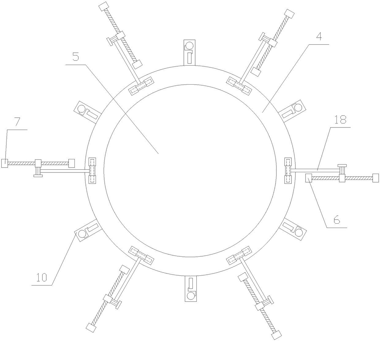
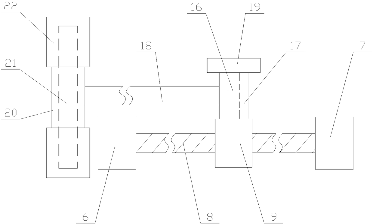
[0032] The present invention is described in further detail now in conjunction with accompanying drawing. These drawings are all simplified schematic diagrams, which only illustrate the basic structure of the present invention in a schematic manner, so they only show the configurations related to the present invention.

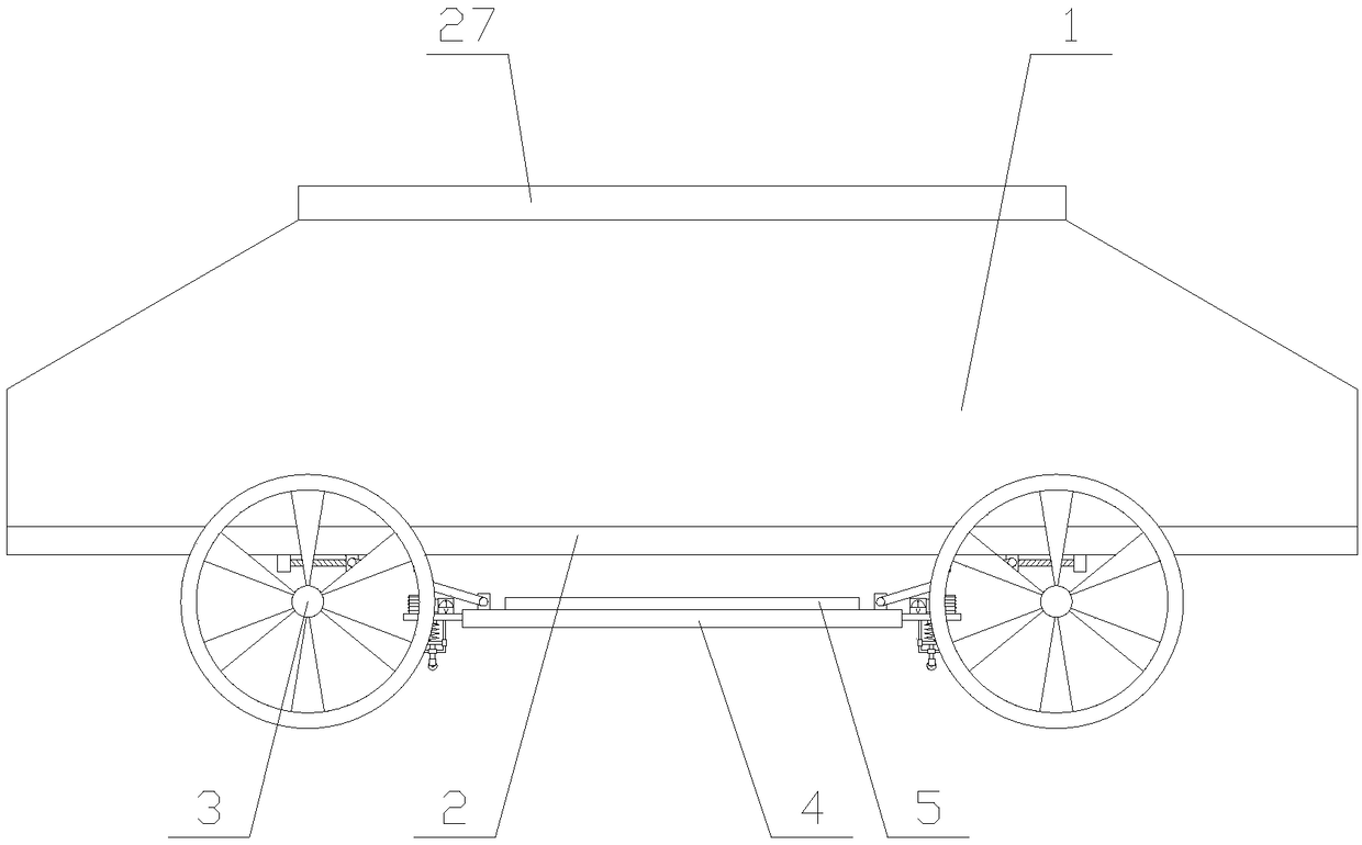
[0033] like figure 1 As shown, an electromagnetic induction type wireless charging car with automatic adjustment function includes a car body 1, a chassis 2 arranged under the car body 1 and four wheels 3 arranged under the chassis 2, and the bottom of the chassis 2 Equipped with a charging mechanism;

[0034]In this new energy vehicle, the charging mechanism under the chassis 2 is close to the road surface, and the energized coil in the road surface provides a magnetic field, so that a current is generated in the charging mechanism to provide energy for the vehicle body 1 to run, and realize the function of charging while driving.

[0035] like figure 2 A...


PUM


Abstract

The invention relates to an electromagnetic induction type wireless charging vehicle with an automatic adjustment function. The vehicle comprises a vehicle body, a chassis and four vehicle wheels; a charging mechanism is arranged below the chassis, the charging mechanism comprises a bottom plate, a charging coil, at least two adjusting mechanisms and at least two testing mechanisms, each adjustingmechanism comprises a motor, buffer blocks, a drive shaft, a slide block and a connecting unit, each testing mechanism comprises side plates, a magnetic field measurement assembly and a height measurement assembly, and each magnetic field measurement assembly comprises a voltmeter and a test coil. The electromagnetic induction type wireless charging vehicle with the automatic adjustment functiondetects the magnetic field distribution situation around the charging coil through the testing mechanism, and further detects the height position of the bottom plate, after the detection is completed,the angle of the bottom plate and the height of the charging coil are adjusted through each adjusting mechanism, so that the charging coil is close to the ground, the charging coil is perpendicular to a magnetic force line of a magnetic field, the magnetic flux in the charging coil is improved, and then the charging efficiency and the practicability of the vehicle are improved.

Description

technical field [0001] The invention relates to the field of new energy vehicles, in particular to an electromagnetic induction wireless charging vehicle with an automatic adjustment function. Background technique [0002] With the rapid development of new energy vehicle technology and wireless charging technology, people combine the two to realize the function of road charging for new energy vehicles. Electric vehicles get rid of the shackles of charging piles and can be driven while driving on the road. Change charging function. The combination of wireless charging and new energy vehicles not only reduces the size of the battery, which helps to reduce the vehicle load, but also greatly improves the battery life of the vehicle. [0003] The main principle of the road surface wireless charging technology for new energy vehicles is to embed coils in the road surface. By passing alternating current to these coils, as the magnitude and direction of the current change, the stre...

Claims


Application Information

Patent Timeline
IPC IPC(8): B60L11/18B60L8/00
CPCB60L8/003B60L53/12B60L53/35B60L53/38Y02T10/70Y02T10/7072Y02T90/12Y02T90/14
Inventor 陈兰
Owner NANJING WEILI INNOVATIVE ENERGY TECH CO LTD
Learn More