Eureka AIR delivers breakthrough ideas for toughest innovation challenges, trusted by R&D personnel around the world.

Working system and method of laser engraving machine based on cloud load balancing control

A laser engraving machine, load balancing technology, applied in general control systems, control/regulation systems, digital control and other directions, can solve the problems of limited computing, processing capacity, difficulty in large-scale application, failure of engraving tasks, etc., to reduce labor management, reducing potential threats, and improving utilization

Active Publication Date: 2018-06-29
XIAMEN UNIV OF TECH
View PDF26 Cites 8 Cited by
  • Summary
  • Abstract
  • Description
  • Claims
  • Application Information

AI Technical Summary

Problems solved by technology

[0010] Based on the above description, laser engraving technology is still a relatively weak field, mainly manifested in: if the host computer uses a PC, there are problems such as bulky, unfavorable to carry, and expensive; if a mobile terminal is used, the computing and processing capabilities are limited , it is difficult to apply on a large scale
The one-to-one connection mode between the upper computer and the lower computer is easy to cause the failure of the engraving task due to the failure of the laser engraving machine or the error of the engraving program

Method used


Image

  • Working system and method of laser engraving machine based on cloud load balancing control
  • Working system and method of laser engraving machine based on cloud load balancing control
  • Working system and method of laser engraving machine based on cloud load balancing control

Examples


Embodiment Construction

[0060] The technical solutions and beneficial effects of the present invention will be described in detail below in conjunction with the accompanying drawings.

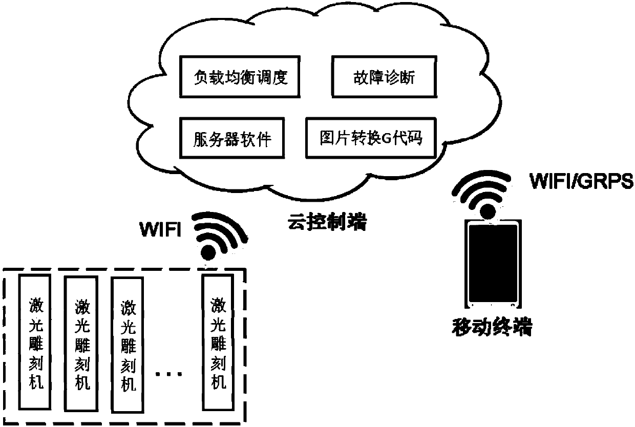
[0061] The present invention provides a laser engraving machine working system based on cloud load balancing control, which includes several laser engraving machines, a cloud control terminal and several mobile intelligent terminals, which will be introduced separately below.

[0062] The laser engraving machine has a built-in controller module, a laser control module, a motor drive module, a wireless transceiver module, a data acquisition module, a power supply module and an auxiliary module. The controller module is the core of the control and data processing of the laser engraving machine; the laser control module is responsible for protecting and driving the laser head; the motor drive module is responsible for driving the X-axis and Y-axis movement of the stepping motor; the wireless The transceiver module is res...


PUM


Abstract

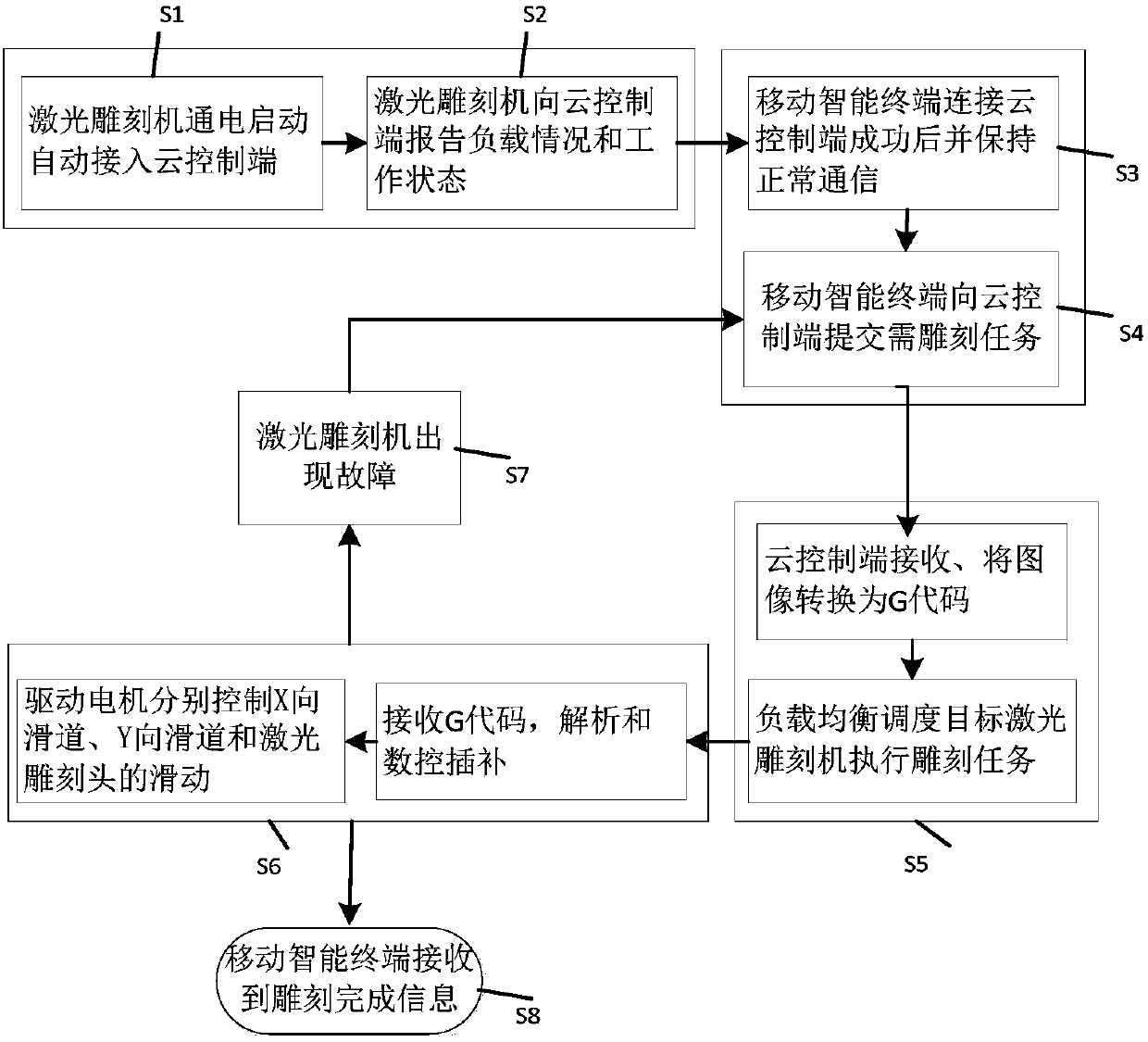
The invention discloses a working system of a laser engraving machine based on cloud load balancing control, and a working method of the laser engraving machine based on cloud load balancing control.The working system comprises a plurality of laser engraving machines, a cloud control terminal and a plurality of mobile intelligent terminals. The working method comprises the following steps of enabling the cloud control terminal to receive an image sent by the mobile intelligent terminal, and converting into a G code; evaluating the load condition of the current global laser engraving machine,finding the target laser engraving machine, and maintaining the load balancing of the system; sending the G code to the target laser engraving machine; dispatching the target laser engraving machine,analyzing, and performing numerical control interpolation, so as to engrave a to-be-processed workpiece. By adopting the technical scheme, the working system and the working method have the advantagesthat by utilizing the cloud terminal to perform distributed type control on the laser engraving machines, the real-time dynamic management and load balancing dispatching on the laser engraving machine are performed; the degree of freedom, portability and maintainability are expanded; the utilization rate of the laser engraving machine is improved; the laser engraving machine is promoted to be greatly applied into the fields of innovation design and artwork design.

Description

technical field [0001] The invention belongs to the technical field of laser engraving, and in particular relates to a cloud-controlled laser engraving machine working system and method. Background technique [0002] Laser engraving machine is a device that uses laser beams to cut or engrave non-metallic materials such as plexiglass, plastic, paper, etc. Under the control of the control system, the drive motor drives the laser engraving head to engrave or engrave the workpiece on the stage. cutting. A conventional laser engraving machine is composed of upper computer software and a lower computer. The upper computer software is responsible for image processing, and issues work instructions to the lower computer and transmits sample trajectory data. The lower computer drive motor controls the X-direction slideway and the sliding of the laser engraving head respectively. Carve the workpiece to be processed. Laser engraving has the advantages of fast speed, high precision, go...

Claims


Application Information

Patent Timeline
IPC IPC(8): G05B19/414
CPCG05B19/4142G05B2219/34013
Inventor 胡建强吴克寿
Owner XIAMEN UNIV OF TECH
Why Eureka
Eureka Blog
Learn More