Cavity filter with cross coupling structure

A cavity filter and cross-coupling technology, applied in the field of communication, can solve problems such as increasing the difficulty of optimization and unfavorable mass production of products, and achieve the effect of reducing production costs and improving production efficiency

Inactive Publication Date: 2018-06-29
HUBEI UNIV
View PDF3 Cites 6 Cited by
  • Summary
  • Abstract
  • Description
  • Claims
  • Application Information

AI Technical Summary

Problems solved by technology

[0005] During the research and practice of the existing technology, the inventors of the present invention found that as the broadband used in the communication industry becomes narrower, the product specifications become more and more stringent. It is necessary to repeatedly modify the length of the fly rod and the height of the fly rod in the cavity to optimize the index. When optimizing the fly rod, it is necessary to consider both the length of the fly rod and the height of the fly rod. During the optimization period, multiple variables are generated. It is determined that optimization takes a lot of time and also increases the difficulty of optimization, which is not conducive to mass production of products

Method used


Image

  • Cavity filter with cross coupling structure
  • Cavity filter with cross coupling structure
  • Cavity filter with cross coupling structure

Examples


Embodiment 1

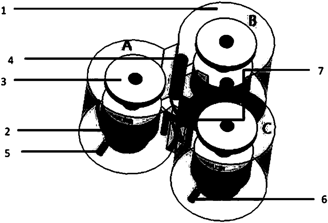
[0018] From figure 1 It can be seen that this is a three-cavity cavity filter, including a circular cavity metal shell 1, a dielectric resonator 2, a dielectric adjustment cover 3, and a metal adjustment rod 4 between adjacent cavities, and the input signal metal Port 5, the output signal metal port 6, the cross-coupling connector connects the AC, and the connector is a metal U-shaped bar 7, which is used to transmit the electromagnetic field between non-adjacent cavities.

[0019] In the three-cavity cavity filter structure, when the coupling is capacitive, a transmission zero will be generated in the low band, thereby enhancing the out-of-band rejection of the low band and enhancing the filtering performance. When the coupling is inductive, the high band will generate a transmission zero, which will enhance the out-of-band rejection of the high band and enhance the filtering performance.

[0020] The cross-coupling structure in the embodiment of the present invention can be...

Embodiment 2

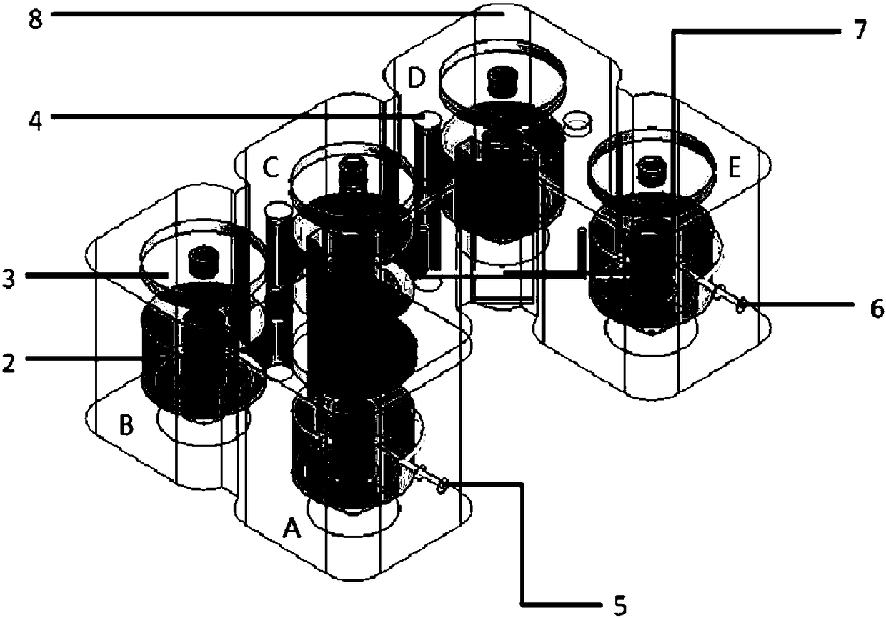
[0023] From figure 2 It can be seen that the shell of this five-cavity cavity filter is a metal square cavity shell 8, and the rest are the same as figure 1 Same as shown. Including shell metal round cavity 8, dielectric resonator, 2, dielectric cover plate 3 for adjusting the electromagnetic field, metal ports 5 and 6 for input and output signals, and metal adjustment rods 4 between adjacent cavities, cross-coupling connection The pieces connect CE, or connect AC or BD, or AD, or BE, and the connecting piece is a metal U-shaped bar 7, which is used to transmit the electromagnetic field between adjacent cavities.

[0024] In this structure, when the coupling is capacitive, a transmission zero will be generated in the low band, thereby enhancing the out-of-band rejection of the low band and enhancing the filtering performance. When the coupling is inductive, the high band will generate a transmission zero, which will enhance the out-of-band rejection of the high band and enh...


PUM


Abstract

The invention discloses a cavity filter with a cross coupling structure. The cavity filter comprises a three-cavity filter and a five-cavity filter, wherein cavities are connected, a dielectric resonant cavity spaced by an isolating wall is arranged in each cavity, a dielectric adjusting cover plate is arranged on the resonant cavity, an input metal port and an output metal port are formed in a pair of adjacent dielectric resonant cavities, and metal adjusting rods are arranged between other adjacent dielectric resonant cavities; a cross coupling connecting piece is arranged between the two non-adjacent dielectric resonant cavities, the connecting piece is a U-shaped metal rod piece, and the cavity bodies and the dielectric resonant cavities are subjected to cross coupling connection by the cross coupling connecting piece and the metal adjusting rods; the electric field formed between the dielectric resonant cavities can be conveniently adjusted by adjusting positions and sizes of theU-shaped metal rod pieces. According to the cavity filter, out-of-band rejection can be enhanced very well, and clutters are eliminated; the coupling structure is low in cost, simple to process, convenient to assemble and suitable for large-scale volume production and application.

Description

technical field [0001] The invention relates to the communication field, in particular to a cavity filter, a cavity filter cross-coupling structure and a base station. Background technique [0002] As a communication signal processing structure, cavity filter is widely used in wireless communication link nodes. In the process of signal transmission and reception in the communication system, the cavity filter has the function of passing signals in specific frequency bands and suppressing out-of-band signals. [0003] As part of communication signal processing, filters are often placed inside the base station or at the antenna. In recent years, based on the requirements of base station transportation and installation and antenna installation, the trend of filter miniaturization and low cost has become more and more obvious. In order to cooperate with the installation of other signal processing components, operators often have certain requirements on the dimensions of the fil...

Claims


Application Information

Patent Timeline
Patent Type & Authority Applications(China)
IPC IPC(8): H01P1/208
CPCH01P1/2084
Inventor 章天金雷泽林郭勤武刘哲伟
Owner HUBEI UNIV
Why Eureka
Try Eureka