A test system and method for mechanical response characteristics of cemented filling body

A technology of cemented filling and response characteristics, applied in the direction of strength characteristics, using stable tension/pressure test material strength, measuring devices, etc., can solve the problems of delay in mining construction period, low efficiency, high manpower and material resources, etc.

Active Publication Date: 2019-01-01
陕西嘉墨能源科技有限公司
View PDF4 Cites 0 Cited by
  • Summary
  • Abstract
  • Description
  • Claims
  • Application Information

AI Technical Summary

Problems solved by technology

However, in the existing technology, the prediction of the mechanical response characteristics of cemented filling bodies is mostly based on experimental testing methods. The test period is long, the efficiency is low, and the cost of manpower and material resources is high, which affects the rapid promotion and application of new cemented filling bodies. Delay in construction period
[0004] In order to solve the above problems, some people explored the method of machine learning, first tested the uniaxial compressive strength of the cemented filling body, and constructed the relationship between the SEM electron microscope scanning image of the cemented filling body and the uniaxial compressive strength; later, the cementation When predicting the mechanical response of the filling body, it is only necessary to collect the SEM electron microscope scanning image, and the computer can be used to make a direct judgment. However, in the actual research and test process, it is found that only testing the uniaxial compressive strength cannot be done well. The research on the mechanical response characteristics of the cemented filling body cannot well meet the actual research and development needs

Method used


Image

  • A test system and method for mechanical response characteristics of cemented filling body
  • A test system and method for mechanical response characteristics of cemented filling body
  • A test system and method for mechanical response characteristics of cemented filling body

Examples


Embodiment Construction

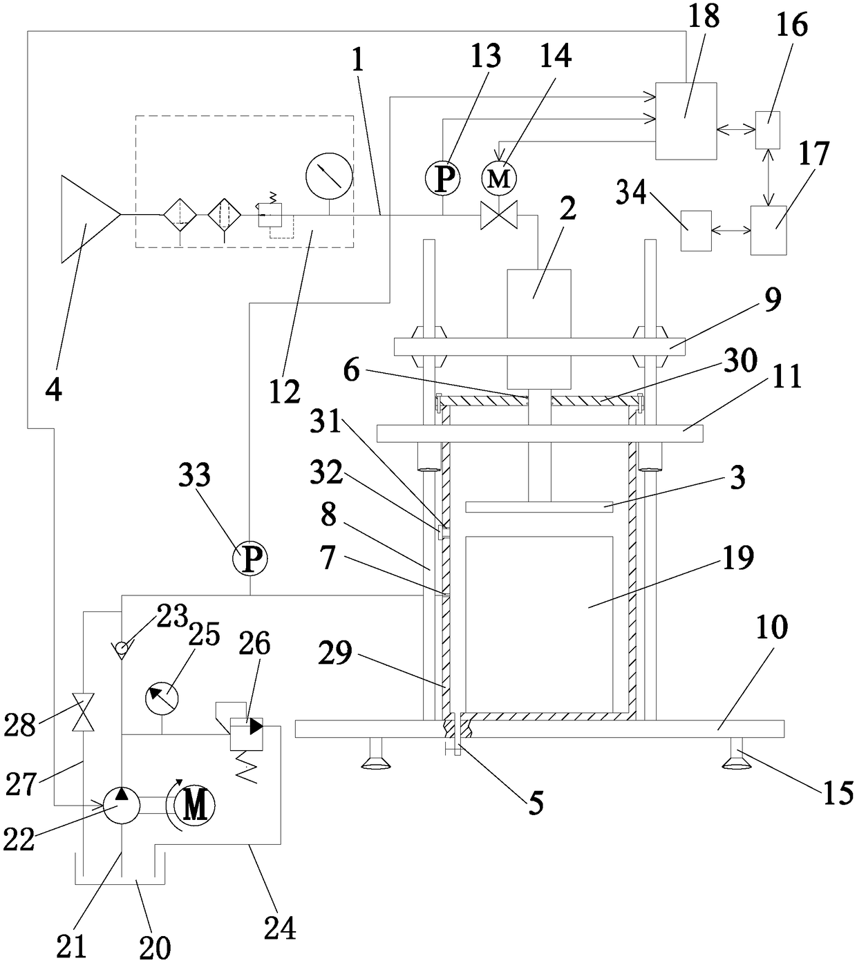
[0075] Such as figure 1 As shown, the mechanical response characteristic test system of the cemented filling body of the present invention includes a cemented filling body triaxial compressive strength testing device, a computer 17 and a SEM scanning electron microscope 34 connected to the computer 17, and the cemented filling body triaxial compressive strength The strength testing device comprises a seat cushion 10 and a plurality of pull rods 8 fixedly connected to the top of the seat cushion 10, a confining pressure loading mechanism for applying confining pressure to the cemented filling body sample, and a confining pressure loading mechanism for providing power to the confining pressure loading mechanism. The pressure loading power system, the axial pressure force transmission mechanism for applying axial pressure to the cemented filling body sample, and the axial pressure force transmission mechanism for providing power to the axial pressure force transmission mechanism; ...


PUM

PropertyMeasurementUnit
heightaaaaaaaaaa

Abstract

The invention discloses a mechanical response characteristic testing system and method for a cemented filling body. The system comprises a cemented filling body three-axis compressive strength testingdevice, a computer and an SEM scanning electron microscope. The method comprises the following steps: I, preparing an SEM sample; II, forming an SEM scanning image; III, carrying out Gaussian filterprocessing on the SEM scanning image; IV, obtaining a plurality of cemented filling body clustering images; V, determining a cemented filling body microcosmic porous image to obtain a cemented fillingbody microcosmic binary image; VI, obtaining a test sample image; VII, normalizing the test sample image; and VIII, inputting the normalized test sample in a pre-established Tensorflow deep learningmechanical response prediction network to obtain a three-axis mechanical response prediction result. According to the method, steps are simple, the prediction efficiency is high and functions are comprehensive, and the method has important meaning on researching strength and stability of the cemented filling body.

Description

technical field [0001] The invention belongs to the technical field of cemented filling mining, and in particular relates to a testing system and method for the mechanical response characteristics of a cemented filling body. Background technique [0002] With the development of national science and technology, the requirements for energy saving and environmental protection technology are getting higher and higher. Traditional cemented backfill mining uses cement as the cementitious material, and the cost of cement is as high as 75% of the total backfill cost. Through research and development, tailings contain active silica and alumina, and using tailings instead of part of cement as cementing material can not only reduce the discharge of tailings, effectively reduce the cost of filling mining, but also improve the strength of the filling body and reduce the ground The collapsed area also plays an active role in promoting the protection of the environment. Therefore, the tai...

Claims


Application Information

Patent Timeline
Patent Type & Authority Patents(China)
IPC IPC(8): G01N3/12G01N3/06G01N23/22
CPCG01N3/06G01N3/12G01N23/22G01N2203/0019G01N2203/0044G01N2203/0048G01N2203/0641
Inventor 刘浪秦学斌张波陈柳王湃张小艳孙伟博王美王燕邱华富
Owner 陕西嘉墨能源科技有限公司
Why Eureka
Try Eureka