
Steel ladle bottom argon blowing gas flow control device and control method

A technology of argon flow and bottom blowing argon, which is applied in the direction of flow control, flow control using electrical devices, non-electric variable control, etc., can solve the problem that the flow rate of argon gas flow at the bottom of the ladle cannot be automatically and accurately controlled, and reduce manual labor. Strength, improved molten steel quality, and improved reliability

Inactive Publication Date: 2018-07-03
SHANGHAI MEISHAN IRON & STEEL CO LTD
View PDF1 Cites 16 Cited by
  • Summary
  • Abstract
  • Description
  • Claims
  • Application Information

AI Technical Summary

Problems solved by technology

[0006] The purpose of the present invention is to provide a control device and control method for the flow rate of argon gas blown at the bottom of the ladle, so as to solve the technical problem that the flow rate of argon gas blown at the bottom of the ladle cannot be automatically and accurately controlled

Method used


Image

  • Steel ladle bottom argon blowing gas flow control device and control method

Examples


Embodiment 1

[0020] Embodiment 1, the method for controlling the flow rate of argon blowing at the bottom of the ladle with the above-mentioned device comprises the following steps:

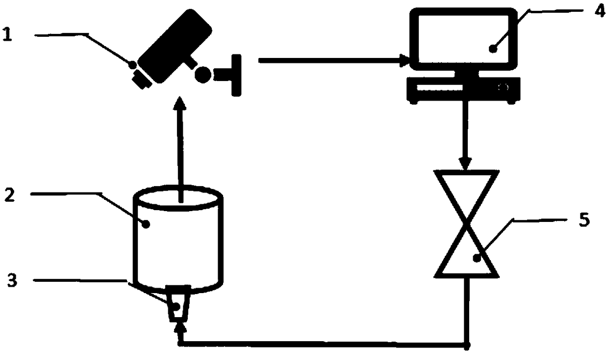
[0021] 1) The image processing and control center server 4 has a database including argon gas flow valve opening, argon gas flow range, ladle bottom argon blowing intensity and molten steel exposure ratio corresponding table, and the image processing and control center server has a ladle Argon blowing strong stirring or weak stirring corresponds to the ratio standard of the exposed surface of molten steel to the molten steel surface: strong stirring means that the exposed area of ​​molten steel accounts for 26-75% of the molten steel surface; weak stirring refers to the ratio of the exposed area of ​​molten steel to the liquid surface of molten steel. 5-25%; violent blowing means that the exposed area of ​​molten steel accounts for more than 75% of the molten steel surface, and violent blowing is not allowed d...

Embodiment 2

[0027] Embodiment 2, the method for controlling the flow rate of argon blowing at the bottom of the ladle with the above-mentioned device, comprising the following steps:

[0028]1) The image processing and control center server 4 has a database including argon gas flow valve opening, argon gas flow range, ladle bottom argon blowing intensity and molten steel exposure ratio corresponding table, and the image processing and control center server has a ladle Argon blowing strong stirring or weak stirring corresponds to the ratio of the exposed surface of molten steel to the molten steel surface: strong stirring means that the exposed area of ​​molten steel accounts for 26-75% of the molten steel surface; weak stirring refers to the ratio of the exposed area of ​​molten steel to the liquid surface of molten steel. 5-25%; violent blowing means that the exposed area of ​​molten steel accounts for more than 75% of the molten steel surface, and violent blowing is not allowed during op...


PUM


Abstract

The invention discloses a steel ladle bottom argon blowing gas flow control device and control method, and solves the technical problem that existing steel ladle bottom argon blowing gas flow cannot be controlled automatically and accurately. The steel ladle bottom argon blowing gas flow control device comprises a camera, a steel ladle, an air brick, an image processing and control center server and an argon gas flow control valve. The camera is arranged above a mouth of the steel ladle; the camera is connected with the image processing and control center server through a cable; the image processing and control center server is connected with the argon gas flow control valve arranged on an argon gas pipeline through a cable; the input end of the argon gas flow control valve is communicatedwith an argon gas source through the argon gas pipeline; the output end of the argon gas flow control valve is communicated with the air brick through the argon gas pipeline; and the air brick is arranged on the bottom portion of the steel ladle. The control device realizes automatic and accurate control of steel ladle bottom argon blowing gas flow, and improves quality of liquid steel.

Description

technical field [0001] The invention relates to a device and method for controlling the flow rate of argon gas blown at the bottom of a ladle, in particular, to a device and a method for controlling the flow rate of argon gas blown at the bottom of a ladle through dynamic images of molten steel and steel slag in the ladle, and belongs to the steelmaking technology field. Background technique [0002] Argon blowing at the bottom of the ladle is a molten steel refining method commonly used in steelmaking production. The molten steel is stirred by blowing argon at the bottom of the ladle to achieve metallurgical functions such as uniform composition and temperature of the molten steel, floating of molten steel inclusions, and desulfurization of the molten steel. Under different metallurgical process conditions, the stirring intensity of bottom blowing argon is different: when desulfurizing the steel slag interface, heating molten steel, and adjusting the alloy, strong stirring...

Claims


Application Information

Patent Timeline
IPC IPC(8): G05D7/06C21C7/072
CPCC21C7/072G05D7/0635
Inventor 张才贵孙玉军郭海滨胡建光
Owner SHANGHAI MEISHAN IRON & STEEL CO LTD
Features
  • Generate Ideas
  • Intellectual Property
  • Life Sciences
  • Materials
  • Tech Scout
  • Unparalleled Data Quality
  • Higher Quality Content
  • 60% Fewer Hallucinations
Learn More