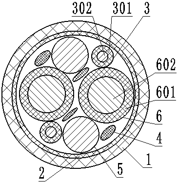
Mooring optical cable capable of keeping power on under condition of drawing

A power-cutting and tethering technology, applied in the direction of extensible conductor cables, communication cables, cables, etc., can solve the problems of small cross-sectional area of ​​electrical units, large outer diameter of composite cables, and power limitations, and achieve functional satisfaction and anti-corrosion The effect of high tensile strength and small outer diameter

Inactive Publication Date: 2018-07-03
东莞市金羽丰知识产权服务有限公司
View PDF6 Cites 0 Cited by
  • Summary
  • Abstract
  • Description
  • Claims
  • Application Information

AI Technical Summary

Problems solved by technology

[0002] At present, there are two main types of photoelectric composite cables in China: one is based on the outdoor optical cable structure as the skeleton, and the electrical unit of the extruded insulating layer is added when the loose tube is cabled, and the inner sheath and armor commonly used in optical cables are added. layer, extruded outer sheath, its disadvantage is that the supply of electric energy is limited, and the cross-sectional area of ​​the electric unit is small; The inner sheath, armor layer, and extruded outer sheath commonly used in power cables have the disadvantage that the outer diameter of the composite cable is larger. The laying methods of these two types of photoelectric composite cables are fixed places such as overhead, through pipes, and buried. , is a commonly used optical cable laying and installation method. In mobile devices and equipment, these two types of photoelectric composite cables cannot be used due to outer diameter, softness and weight restrictions, especially the weight and weight of the product for aviation aerostats. The softness requirements are higher, and the structure can only be specially designed to meet the needs of devices and equipment. For this reason, we propose to draw and uninterrupted power-type tethered optical cables, and at the same time, it is necessary to allow the tethered optical cables to be able to withstand radial stretching. ensure power supply

Method used


Image

  • Mooring optical cable capable of keeping power on under condition of drawing

Examples


Embodiment 1

[0018] The composition of the nanofluid is: 50 parts by weight of nano-carbon powder, 50 parts by weight of nano-copper powder, 70 parts by weight of flake graphite powder, 30 parts by weight of nano-bismuth alloy, and the powder particle size of nano-carbon powder is 120 nm to 300 nm. The particle size of the nano copper powder is 20 to 100 nanometers, and the particle size of the nano bismuth alloy powder is 100 to 300 nanometers.

Embodiment 2

[0020] The composition of the nanofluid is: 30 parts by weight of nano-carbon powder, 60 parts by weight of nano-copper powder, 60 parts by weight of flake graphite powder, 30 parts by weight of nano-bismuth alloy, and the powder particle size of nano-carbon powder is 120 nm to 300 nm. The particle size of the nano copper powder is 20 to 100 nanometers, and the particle size of the nano bismuth alloy powder is 100 to 300 nanometers.

Embodiment 3

[0022] The composition of the nanofluid is: 30 parts by weight of nano-carbon powder, 60 parts by weight of nano-copper powder, 60 parts by weight of flake graphite powder, and 10 parts by weight of nano-bismuth alloy. The powder particle size of nano-carbon powder is 120 nm to 300 nm. The particle size of the nano copper powder is 20 to 100 nanometers, and the particle size of the nano bismuth alloy powder is 100 to 300 nanometers.

[0023] The principle and advantages of the present invention: The difference from the previous photoelectric composite cable is that the power supply of the photoelectric composite cable used before is limited, the cross-sectional area of ​​the electrical unit is small, and the outer diameter is relatively large. The previous photoelectric composite cable laying method is overhead, through pipe Fixed places such as ground, buried, etc., are commonly used optical cable laying and installation methods. In devices and equipment that can be used, these t...


PUM

PropertyMeasurementUnit
thicknessaaaaaaaaaa
thicknessaaaaaaaaaa
sizeaaaaaaaaaa

Abstract

The invention discloses a photoelectric composite cable, and specifically relates to a mooring optical cable capable of keeping power on under the condition of drawing. The mooring optical cable comprises an outer sheath and a polyester belt. The outer sheath is arranged in an extruding manner outside the polyester belt. Two electrical signal lines, four aramid yarns, two optical units and two power lines are arranged inside the polyester belt. The two electrical signal lines, the four aramid yarns, the two optical units and the two power lines are twisted into a cable in a certain direction,and are wrapped in the polyester belt. Nanofluids are used as a conductor, and the nanofluids are composed of, by weight, 30-60 parts of nano carbon powder, 40-60 parts of nano copper powder, 60-80 parts of flaky graphite powder and 10-30 parts of nano bismuth alloy.

Description

Technical field [0001] The invention relates to a photoelectric composite cable, in particular to a drawn uninterrupted power type tethered optical cable. Background technique [0002] At present, there are two main types of photoelectric composite cables in China: one type is an electrical unit with an outdoor optical cable structure as the skeleton, and an extruded insulation layer is added when the loose tube is formed into the cable, and the inner sheath and armor commonly used for optical cables are added. The disadvantage is that the power supply is limited and the cross-sectional area of ​​the electric unit is small; the other is based on the low-voltage power cable, and the optical unit structure is added when the insulated core is formed into the cable. The inner sheath, armor layer and extruded outer sheath are commonly used in power cables. Its disadvantage is that the outer diameter of the composite cable is large. The two types of photoelectric composite cables are l...

Claims


Application Information

Patent Timeline
Patent Type & Authority Applications(China)
IPC IPC(8): H01B11/22H01B3/42H01B1/04H01B7/06
CPCH01B11/22H01B1/04H01B3/421H01B7/06
Inventor 陈建中岳同海黎鹏黄斌
Owner 东莞市金羽丰知识产权服务有限公司
Why Eureka
Try Eureka