Six-degree-of-freedom ultralow frequency vibration isolation device based on zero stiffness system and control system thereof
A zero-stiffness, degree-of-freedom technology, applied in the field of six-degree-of-freedom vibration isolation devices and their control systems, can solve problems such as few studies, and achieve the effect of low cost and simple structure
- Summary
- Abstract
- Description
- Claims
- Application Information
AI Technical Summary
Problems solved by technology
Method used
Image
Examples
specific Embodiment approach 1
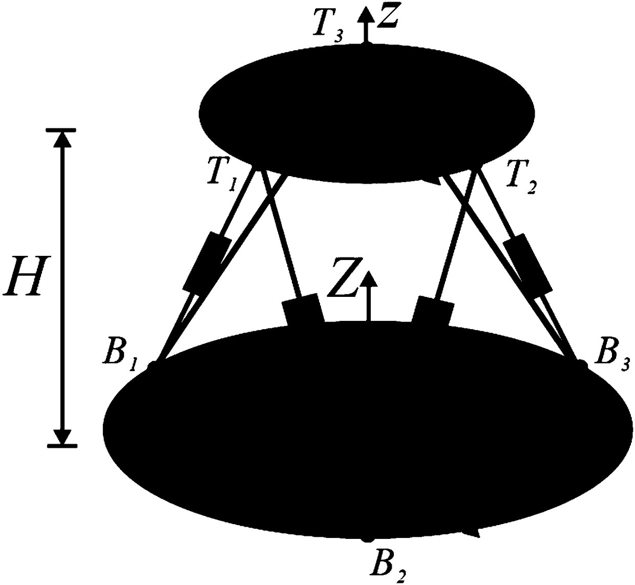
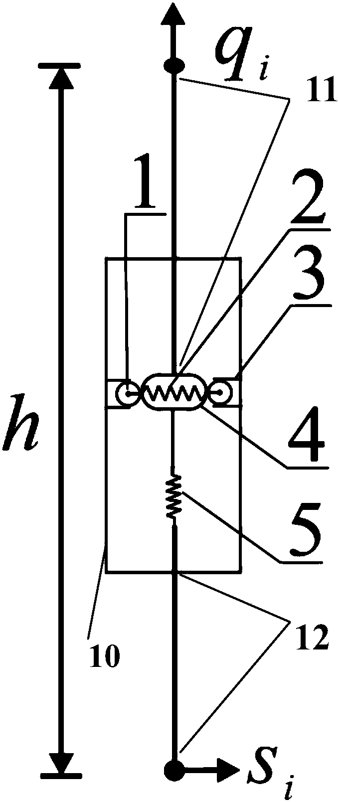
[0059] Specific implementation manner one: such as figure 1 , figure 2 with Figure 7 As shown, the scheme of the present invention will be described in detail with reference to the accompanying drawings:
[0060] A type of six-degree-of-freedom ultra-low frequency vibration isolation device based on a zero-stiffness system. The zero-stiffness system refers to a system that does not have the ability to resist elastic deformation and has continuous balance, constant potential energy, and neutral stability. Its dynamic equation can be expressed for
[0061]
[0062] Where X is the displacement vector of the system, and ε is the acceleration vector; the zero-stiffness system has the characteristic of zero natural frequency, which can achieve low-frequency, ultra-low frequency, and even low-to-zero frequency vibration immunity and vibration isolation performance;
[0063] The configuration of the six-degree-of-freedom ultra-low frequency vibration isolation device (six-degree-of-freedo...
specific Embodiment approach 2
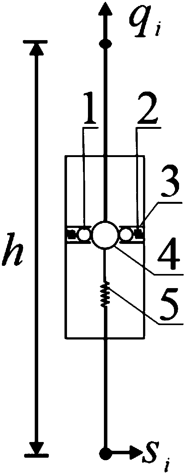
[0097] Specific implementation manner two: such as figure 1 with image 3 As shown, other specific implementation schemes of a single vibration isolation module are given:
[0098] The connecting assembly between the springs includes two rollers 1, two guide rails 3, and an intermediate wheel 4, and the horizontal spring includes two horizontal compression springs 2;
[0099] Two guide rails 3 are respectively fixed on the middle of the inner wall of the cylindrical shell 10, and the two are symmetrically distributed. Each roller 1 is placed in the corresponding guide 3, and each roller 1 is arranged between each roller 1 and the inner wall of the corresponding cylindrical shell 10. There is a horizontal compression spring 2, the middle wheel 4 is located between the two rollers 1, the upper part of the middle wheel 4 is fixedly connected to the lower end of the upper link 11, the lower part of the middle wheel 4 is fixedly connected to the upper end of the vertical spring 5. 4 Un...
specific Embodiment approach 3
[0106] Specific implementation manner three: such as figure 1 with Figure 4 As shown, other specific implementation schemes of a single vibration isolation module are given:
[0107] The connecting assembly between the springs includes two sliders 1, two guide rails 3, and two connecting rods 4, and the horizontal spring includes two horizontal compression springs 2;
[0108] Two guide rails 3 are respectively fixed on the middle of the inner wall of the cylindrical shell 10, and they are symmetrically distributed. Each slider 1 is placed in the corresponding guide rail 3, and each slider 1 and the inner wall of the corresponding cylindrical shell 10 There is a horizontal compression spring 2 in between. One end of each connecting rod 4 is hinged with the center of the corresponding slider 1, and the other end of the two connecting rods 4 is hinged, and the two connecting rods 4 are located between the two sliders 1.
[0109] The hinged parts of the two connecting rods 4 are connec...
PUM
 Abstract
Description
Claims
Application Information
 - R&D
- Intellectual Property
- Life Sciences
- Materials
- Tech Scout
- Unparalleled Data Quality
- Higher Quality Content
- 60% Fewer Hallucinations
Browse by: Latest US Patents, China's latest patents, Technical Efficacy Thesaurus, Application Domain, Technology Topic, Popular Technical Reports.
© 2025 PatSnap. All rights reserved.Legal|Privacy policy|Modern Slavery Act Transparency Statement|Sitemap|About US| Contact US: help@patsnap.com


