A Method for Realizing Panoramic Multipoint Roaming

A panorama, multi-point technology, applied in 3D image processing, instruments, computing and other directions, can solve the problem that a single jump browsing cannot meet the seamless virtual roaming and other problems

Active Publication Date: 2021-05-11
GUANGDONG SANWEIJIA INFORMATION TECH CO LTD
View PDF5 Cites 0 Cited by
  • Summary
  • Abstract
  • Description
  • Claims
  • Application Information

AI Technical Summary

Problems solved by technology

This kind of virtual roaming system built by collecting and shooting pictures at fixed points into a panorama, and then integrating a specific algorithm, its single-jump browsing cannot satisfy the seamless virtual roaming of user-defined routes

Method used


Image

  • A Method for Realizing Panoramic Multipoint Roaming
  • A Method for Realizing Panoramic Multipoint Roaming
  • A Method for Realizing Panoramic Multipoint Roaming

Examples


Embodiment 1

[0039] see Figure 1-3 , the present invention provides a technical solution: a method for realizing panoramic multi-point roaming, the specific steps of the method for realizing panoramic multi-point roaming are as follows:

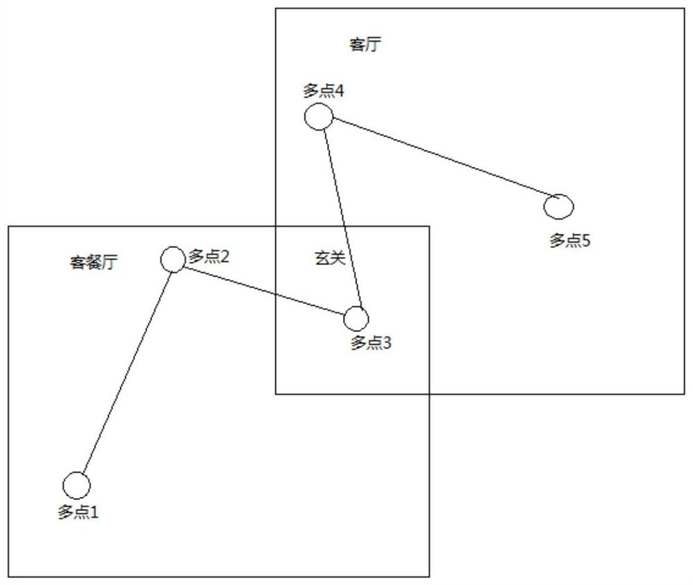
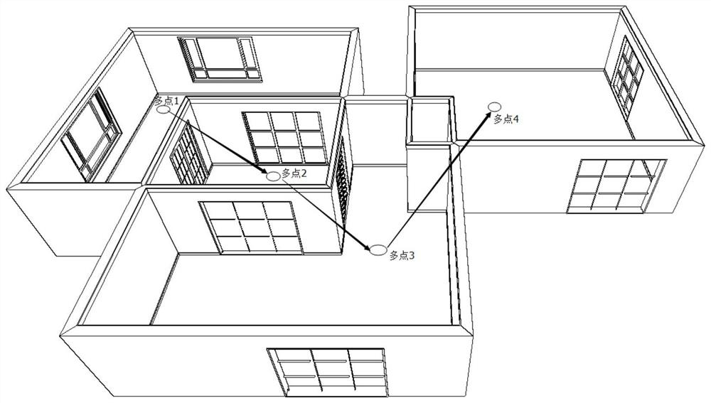
[0040] S1: Draw the roaming path. On the planar design of the panorama scheme, draw the virtual position point for roaming in each space. This point represents the position of the camera in this space. Scene drawing points, from the starting point to the end point, draw roaming points in turn to form a complete roaming path. During the actual roaming process, you will freely switch scenes according to the drawn path;

[0041] S2: Render the panorama. According to the designed panorama plan, render the cross-shaped panorama. Each space corresponds to the segmentation map of 6 faces and the preview image of the current panorama plan. The rendered map is stored on the server, and the corresponding path is recorded for panorama display. The engine obtains t...


PUM


Abstract

The invention discloses a method for realizing panoramic multi-point roaming. The specific steps of the method for realizing panoramic multi-point roaming are as follows: S1: drawing a roaming path, S2: rendering a panoramic image, S3: collecting coordinates, S4: generating a panoramic file, S5 : Obtain the position of the spatial point, S6: Draw a multi-point path. The present invention selects the cube panorama as the research target. Because the cube panorama has a simple structure, it is conducive to image storage and compression, and is more suitable for free switching between multiple spaces, which is beneficial to panoramas. Freely specify the virtual roaming of the roaming route to achieve a seamless multi-scenario immersive experience. In the expression of the actual 3D roaming scene, the switching of multiple scenes is converted into a visual drawing operation. For different roaming scenes, different custom roaming route strategies are adopted. , to achieve high-quality virtual panorama roaming drawing.

Description

technical field [0001] The invention relates to the technical field of tile multi-brick paving, in particular to a method for realizing panoramic multi-point roaming. Background technique [0002] Virtual reality technology is an emerging technology developed in the past 30 years. It integrates information technologies such as machine vision, computer graphics drawing, sensors, 3D simulation and artificial intelligence to build virtual scenes and support user interaction, so as to realize user identity. The purpose of immersive observation and even control of scene information. A virtual reality system must meet three characteristics: conception, immersion, and interaction. Due to the limitation of computer performance (computing power, storage capacity), the three-dimensional scene drawn by computer graphics is usually rough, which cannot provide enough immersion and full interactivity. At present, based on the rapid development of image rendering technology, it provides ...

Claims


Application Information

Patent Timeline
Patent Type & Authority Patents(China)
IPC IPC(8): G06T19/00G06T15/00
CPCG06T15/005G06T19/006
Inventor 卢健智龚德明何为
Owner GUANGDONG SANWEIJIA INFORMATION TECH CO LTD
Why Eureka
Try Eureka