

Water treatment process
A unit treatment, water flow technology, applied in mining wastewater treatment, non-polluting water treatment, water/sewage treatment, etc., can solve problems such as consumption of chemicals
- Summary
- Abstract
- Description
- Claims
- Application Information
AI Technical Summary
Problems solved by technology
Method used
Image

Examples
Embodiment 1
[0092] In this trial, tar sands produced water was treated by an enhanced electrocoagulation (EC) method. A small laboratory-scale EC unit consisting of a cylindrical acrylic housing and metal electrodes was used. Six medium carbon steel electrodes measuring 110 mm x 90 mm x 2 mm were used as anodes and six stainless steel (SS 316) electrodes measuring 110 mm x 90 mm x 1 mm were used as cathodes in the EC cell. The anode and cathode electrodes were assembled in an alternating sequence with a 6mm gap between electrodes. A DC power supply is used to apply DC current to the EC unit.
[0093] Different sets of treatments were tested by the EC method on produced water containing very high levels of silica and organic color. The DC current was varied between 1.5 amps and 3.5 amps, and the dwell time in the test was 30 minutes. In the EC method, the formation of two kinds of sludge was observed, the light sludge containing organic impurities floating on the water surface, which wa...
Embodiment 2
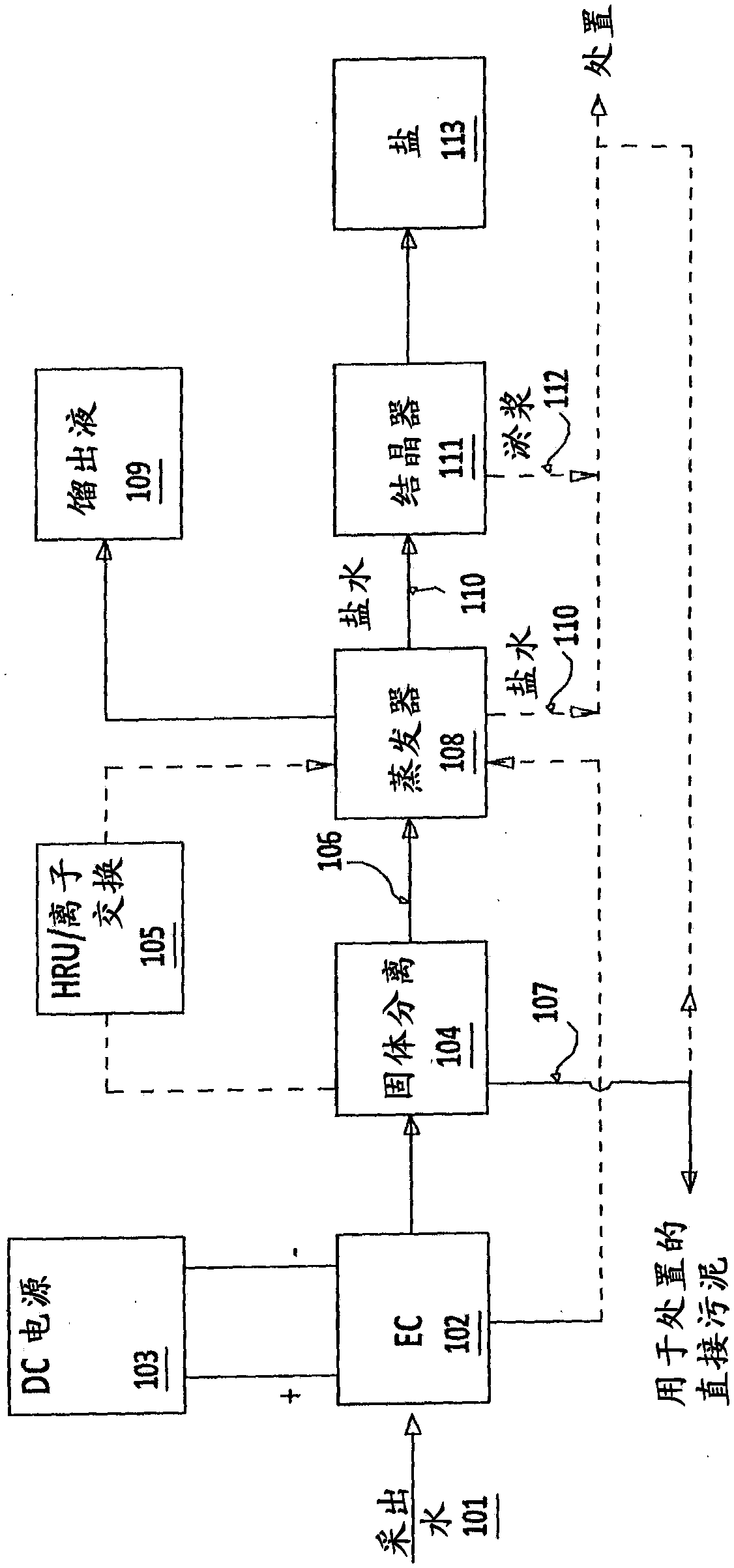
[0104] In this experiment, as figure 1 As shown (treatment scheme 1), the produced water from tar sands is treated. The tar sands produced water was first treated by the EC method by means of the EC unit used in Example 1. The operating conditions, treated water quality and impurity removal efficiency of the EC process are summarized in Tables 4 and 5.
[0105] Table 4: Operating conditions of the EC unit
[0106]
[0107]
[0108] Table 5: Quality and removal efficiency of water treated by the EC method
[0109]
[0110] After solids separation, the EC treated water was passed through a sodium zeolite-based hardness removal unit (HRU) to remove residual hardness, after which the residual hardness of the outlet water was reduced to less than 1 ppm. Finally, the treated water is evaporated in an evaporator and 97% of the water (distillate) is recovered. The brine from the evaporator is further concentrated to the crystallization stage. The salt was light brown in co...
Embodiment 3
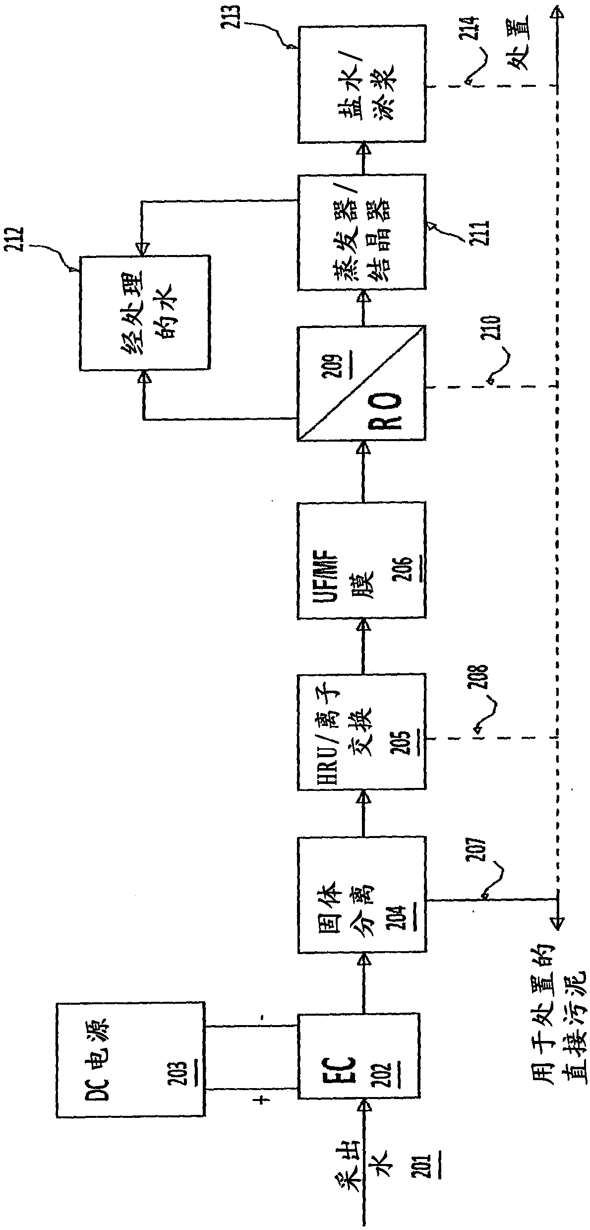
[0118] In this experiment, following the EC method, tar sands produced water was treated by a membrane-based method ( figure 2 ). The produced water is first treated by the EC method, where most of the impurities are removed. EC treated water contains less than 5 ppm silica, less than 10 NTU turbidity and very low levels of residual hardness. The EC treated water is then passed through a zeolite-based SAC-based HRU unit and a polymeric ultrafiltration membrane to remove residual hardness and turbidity. The outlet water from these units contained less than 1 ppm hardness and less than 0.1 NTU turbidity. The treated water in this step meets all requirements for further treatment by reverse osmosis. Finally, the water can be passed through a RO membrane based on the membrane manufacturer's guidelines, resulting in permeate and greater than 90% recovery for further utilization. The experimental results in each step are summarized in Tables 8 and 9.
[0119] Table 8: Treated ...
PUM
| Property | Measurement | Unit |
|---|---|---|
| hardness | aaaaa | aaaaa |
| recovery rate | aaaaa | aaaaa |
Abstract
Description
Claims
Application Information