
Internal combustion engine particle filter control system

A particle filter and control system technology, applied to internal combustion piston engines, combustion engines, machines/engines, etc., can solve the problems of less correction, limited accuracy, and no consideration, so as to improve reliability and accuracy, and improve system safety. performance, cost reduction

Active Publication Date: 2018-07-13
CHINA FIRST AUTOMOBILE
View PDF9 Cites 10 Cited by
  • Summary
  • Abstract
  • Description
  • Claims
  • Application Information

AI Technical Summary

Problems solved by technology

[0006] 1. After the incomplete regeneration of the particulate filter, the particle distribution state is a non-uniform distribution state, and the corresponding relationship between pressure difference and accumulation amount is no longer the same as that of the uniform distribution state. If the distribution state is not considered to be corrected, the particle accumulation amount will occur Estimation error, which in turn affects the correct calculation of the regeneration timing of the particulate filter, and there is a risk of thermal runaway during regeneration of the particulate filter;
[0007] 2. When using the engine speed and fuel injection volume as the conditions for calculating particulate emissions, the influence of the cooling water temperature of the internal combustion engine on its particulate emissions during the actual operation of the internal combustion engine is not considered
[0008] 3. It does not consider that when the differential pressure sensor fails, the second method of calculating the accumulated amount of particulates or the second method has less correction amount and limited accuracy, and cannot provide accurate regeneration opportunities for the particulate filter

Method used


Image

  • Internal combustion engine particle filter control system
  • Internal combustion engine particle filter control system
  • Internal combustion engine particle filter control system

Examples


Embodiment Construction

[0041] The present invention will be further described below in conjunction with specific drawings and embodiments.

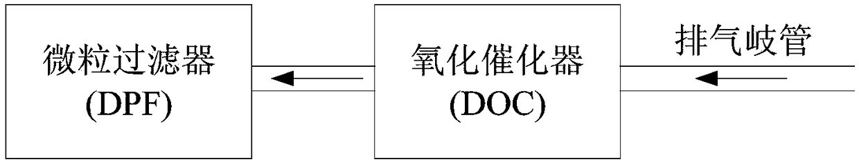
[0042] figure 1 Among them, the exhaust gas of the internal combustion engine passes through the exhaust manifold first through the oxidation catalyst (DOC for short), and then through the particulate filter (also known as the particulate filter, DPF for short) to meet the national exhaust emission standards.

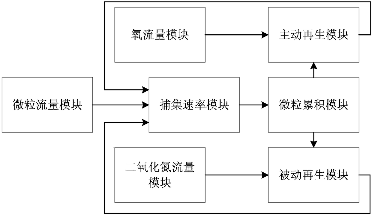
[0043] figure 2 It is a schematic diagram of the internal combustion engine particulate filter control system. The particulate filter control system of an internal combustion engine includes a particulate flow module, an oxygen flow module, a nitrogen dioxide flow module, an active regeneration module, a passive regeneration module, a capture rate module and a particulate accumulation module.

[0044] The particle flow module is used to calculate the particle emission flow of the exhaust gas of the internal combustion engine before treatment;

[0045...


PUM


Abstract

The invention provides an internal combustion engine particle filter control system. The control system comprises a particle flow module, an oxygen flow module, a nitrogen dioxide flow module, an active regeneration module, a passive regeneration module, a capturing speed module and a particle accumulation module; the particle flow module is used for calculating a flow of particles entering a particle filter; the oxygen flow module is used for calculating a flow of oxygen entering the particle filter; the nitrogen dioxide flow module is used for calculating a flow of nitrogen dioxide enteringthe particle filter; the active regeneration module is used for calculating an active regeneration reaction speed of the particle filter; the passive regeneration module is used for calculating a passive regeneration reaction speed of the particle filter; the capturing speed module determines a particle accumulation speed in the particle filter according to the particle flow and the regeneration reaction speed; and the particle accumulation module determines a particle accumulation quantity in the particle filter according to a particle accumulation speed integral. The control system can precisely calculate the load of the particles in the internal combustion engine particle filter under the condition of not depending on pressure or pressure difference sensor.

Description

technical field [0001] The invention relates to the field of internal combustion engines, in particular to a diesel engine energy saving and emission reduction system. Background technique [0002] Solution 1: Chinese patent CN1304743C provides an engine exhaust gas cleaning component, and its control method includes a method for estimating the carbon load of the particulate filter. The technical means adopted by this patent and the effect achieved are: the engine control unit estimates the particulate accumulation of the particulate filter based on the difference between the upstream pressure and the downstream pressure of the particulate filter, and recommends using the exhaust gas flow rate adjustment obtained from the engine speed and load by looking up the chart Estimated particulate accumulation. The deficiency of this patent and the reason is that when only the differential pressure is used as a method for estimating the accumulation of particulates, the influence of...

Claims


Application Information

Patent Timeline
Patent Type & Authority Applications(China)
IPC IPC(8): F01N9/00F01N11/00
CPCF01N9/002F01N11/00F01N2900/14F01N2900/1402F01N2900/1611Y02T10/40
Inventor 马涛顾欣王伏龚笑舞周奇王维居钰生
Owner CHINA FIRST AUTOMOBILE
Learn More