
Vacuum sintering furnace for manufacturing self-lubricating work piece

A vacuum sintering furnace and vacuum furnace technology, applied in the field of vacuum sintering furnaces and composite double-sided workpieces, can solve the problems of cumbersome process, loose molecular structure of sintered layer, increased deformation, etc., and achieve the effect of reducing cumbersome process

Pending Publication Date: 2018-07-13
苏州金言来真空炉业有限公司
View PDF6 Cites 8 Cited by
  • Summary
  • Abstract
  • Description
  • Claims
  • Application Information

AI Technical Summary

Problems solved by technology

[0006] 1. Since the workpiece of the mesh belt furnace is always kept in the running state, the powder on the sintered surface is always kept in a loose state and there is no way to apply pressure on the upper part to compact it, so the molecular structure of the sintered layer is loose and cannot be densified. The process of this product also needs to carry out cold rolling process, and carry out multiple sintering and rolling, so on the one hand, the process is cumbersome, on the other hand, it also greatly wastes energy consumption and increases production costs.
[0007] 2. Since the sintering is carried out in the free state of the high-temperature workpiece, all the sintered products, including the base material and the sintered layer, often have a large amount of deformation, which brings great trouble to gold processing, and due to the deformation amount Increased loss also increases
Therefore, on the one hand, the sintered layer needs to be given a certain pressure, and the pressure control on the surface of the sintered layer has not been reported in this regard, and due to multiple sintering and rolling, the production cost is quite high and the market competitiveness is poor.

Method used

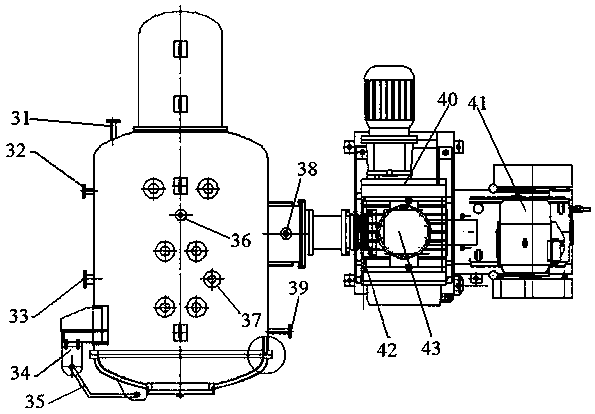
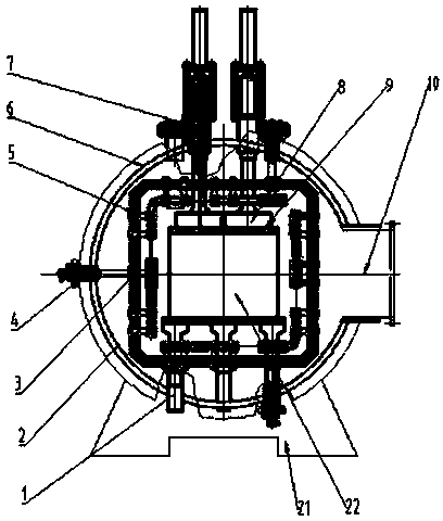
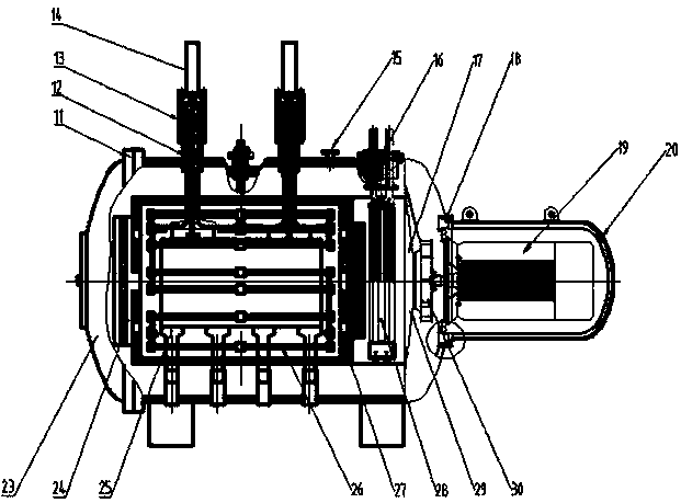

Image

  • Vacuum sintering furnace for manufacturing self-lubricating work piece
  • Vacuum sintering furnace for manufacturing self-lubricating work piece
  • Vacuum sintering furnace for manufacturing self-lubricating work piece

Examples


Embodiment Construction

[0041] In order to enable those skilled in the art to better understand the technical solutions in the present invention, the technical solutions in the embodiments of the present invention will be clearly and completely described below in conjunction with the drawings in the embodiments of the present invention. Obviously, the described The embodiments are only some of the embodiments of the present invention, not all of them. Based on the embodiments of the present invention, all other embodiments obtained by persons of ordinary skill in the art without making creative efforts shall fall within the protection scope of the present invention.

[0042] It should be noted that when an element is referred to as being “disposed on” another element, it may be directly on the other element or there may also be an intervening element. When an element is referred to as being "connected to" another element, it can be directly connected to the other element or intervening elements may a...


PUM

PropertyMeasurementUnit
thicknessaaaaaaaaaa

Abstract

The invention discloses a vacuum sintering furnace for manufacturing a self-lubricating work piece. The vacuum sintering furnace comprises a vacuum furnace body, a furnace container and a pressure applying mechanism, wherein the vacuum furnace body communicates with exhaust equipment; the furnace container is positioned inside the vacuum furnace body; the furnace container is provided with a heating element for sintering the self-lubricating work piece; the pressure applying mechanism is connected with the furnace container; and the pressure applying mechanism can be used for applying pressureto the surface of the self-lubricating work piece. The furnace container is also internally provided with a support seat for supporting the lower surface of the self-lubricating work piece; the pressure applying mechanism comprises a pressing head and a push component, wherein the pressing head is positioned inside the furnace container and can be used for pressing down the upper surface of the self-lubricating work piece; the push component is connected with the pressing head; the push component comprises a lifting cylinder sleeve and a cylinder, wherein the lifting cylinder sleeve is arranged on the wall of the furnace container and the container wall of the vacuum furnace body in a penetration manner; and the cylinder is positioned outside the vacuum furnace body. The vacuum sinteringfurnace for manufacturing the self-lubricating work piece implements a process by one-time sintering and reduces cumbersome processes of multi-time rolling and sintering.

Description

technical field [0001] The invention belongs to the field of self-lubricating workpiece manufacturing industry, and in particular relates to a vacuum sintering furnace for making self-lubricating workpieces, especially suitable for making a composite type of sintering copper, iron and other alloy powders on steel plates or steel bushings and containing solid lubricants For double-sided workpieces, the thickness of the sintered layer is generally between 1-5mm. Background technique [0002] The current bimetallic self-lubricating bearings are manufactured in a variety of ways, such as ordinary melting casting method, centrifugal casting method, mesh belt continuous sintering method, etc. [0003] Ordinary melting casting is generally to cast melted tin bronze 663 on the surface of the steel plate. This melting casting method is more common, but its disadvantages are that the bonding strength of the double layer is poor, the molecular structure of the cast material is loose, a...

Claims


Application Information

Patent Timeline
Patent Type & Authority Applications(China)
IPC IPC(8): F27B21/00F27D7/06F27D9/00F27D19/00
CPCF27B21/00F27D7/06F27D9/00F27D19/00F27D2019/0003F27D2007/066F27D2009/0013F27D2009/0005
Inventor 李荣华
Owner 苏州金言来真空炉业有限公司
Learn More