
Heat transport device and projector

A technology for heat transfer and projectors, applied in the field of projectors, can solve the problems of shortened start-up time, time-consuming, heating and temperature of electronic components, etc.

Active Publication Date: 2018-07-13
SEIKO EPSON CORP
View PDF8 Cites 8 Cited by
  • Summary
  • Abstract
  • Description
  • Claims
  • Application Information

AI Technical Summary

Problems solved by technology

[0006] However, in Patent Document 1, there are problems such as that a heat storage material is required in addition to the loop-type heat pipe, and it is difficult to cope with a variable calorific value.
Also, in Patent Document 2, the heating device is used to heat the steam pipe to prevent condensation in the steam pipe. Although this technique contributes to the stable operation of the loop-type heat pipe, it is not ideal in terms of shortening the start-up start time.
[0007] In addition, when the start-up of the loop-type heat pipe takes time, there is a problem that the heat generation temperature of the electronic component to be cooled is overshooted.
In addition, there is a problem that the loop type heat pipe does not start up when the amount of heat generated by the electronic component is small, or when the influence of heat leakage is large.

Method used


Image

  • Heat transport device and projector
  • Heat transport device and projector
  • Heat transport device and projector

Examples


no. 1 Embodiment approach 〕

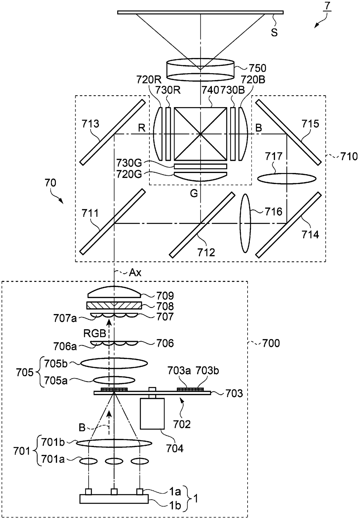
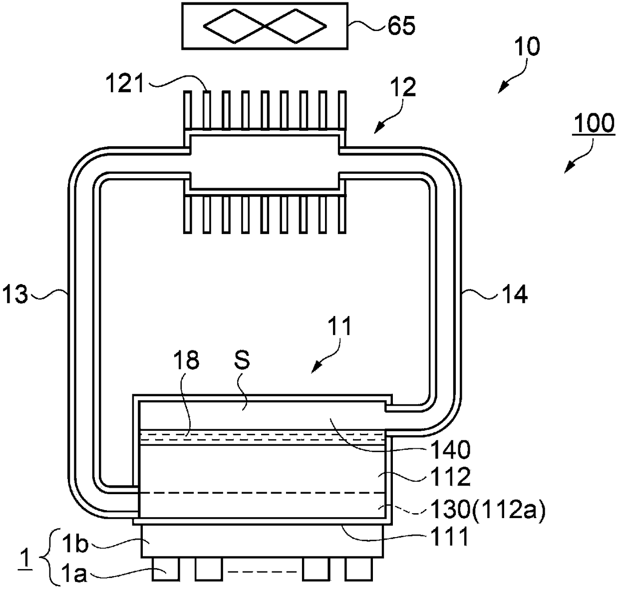
[0038] figure 1 It is a diagram showing the configuration of the optical system 70 of the projector 7 according to the first embodiment. In addition, the optical system 70 of the projector 7 according to the present embodiment is constituted by using the light source device 1 composed of a laser light source 1a and the light modulation device composed of a transmissive liquid crystal panel. refer to figure 1 The configuration of the optical system 70 of the projector 7 will be described. In addition, the heat transport device 100 of the present invention is configured as a device for cooling the light source device 1 to be cooled. The content of the heat transport device 100 will be described later.

[0039] Such as figure 1 As shown, the projector 7 has: an illumination device 700 ; a color separation optical system 710 ; three liquid crystal panels 730R, 730G, and 730B as light modulation devices; a color synthesis device 740 ; and a projection optical system 750 .

[0...

no. 2 Embodiment approach 〕

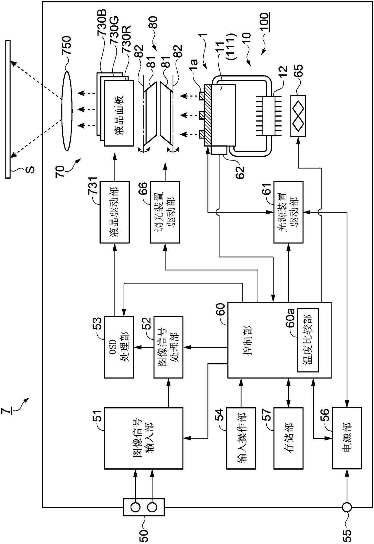
[0125] Figure 6 It is a diagram schematically showing a schematic configuration of a circuit of a projector 7A according to the second embodiment. refer to Figure 6 The circuit configuration of projector 7A of this embodiment will be described.

[0126] In addition, the circuit configuration of the projector 7A according to the present embodiment is different from the circuit configuration of the projector 7 according to the first embodiment in the following points, and other configuration parts are the same. In addition, the same code|symbol as 1st Embodiment is attached|subjected to the same structural part or the structural part which performs the same operation.

[0127] The projector 7 of the first embodiment has the temperature detection unit 62 and the control unit 60 (temperature comparison unit 60a), but the projector 7A of the present embodiment does not have the temperature detection unit 62 and the temperature comparison unit 60a, but has an elapsed time The m...


PUM


Abstract

A heat transport device which reduces the startup time of a loop heat pipe, and a projector having a heat transport device are provided. A heat transport device includes a loop heat pipe configured inthe form of a loop, and a control unit configured to control an amount of heat generated by a heat generating part when the loop heat pipe starts up. The loop heat pipe includes an evaporating unit configured to receive heat of a heat generating part as a cooling target and evaporate a hydraulic fluid, a condensing unit configured to radiate heat and condense vapor obtained by evaporation of thehydraulic fluid, a vapor pipe which connects the evaporating unit and the condensing unit to each other, and a liquid pipe which connects the condensing unit and the evaporating unit to each other.

Description

technical field [0001] The invention relates to a heat delivery device and a projector having a heat delivery device. Background technique [0002] Conventionally, loop-type heat pipes are known as cooling devices used in various electronic devices. The loop type heat pipe includes: an evaporating part that evaporates the working fluid by heat from a heating element; a condensing part that radiates heat from the evaporated working fluid to condense the steam; and a steam pipe and a liquid pipe that connect the evaporating part It is connected with the condensation part to form a loop. In such a loop-type heat pipe, since the cooling cycle is not established until the working fluid present in the steam flow path in the evaporator is completely evaporated, it takes time to start up. [0003] Patent Document 1 discloses a technology for shortening the start-up time of a loop-type heat pipe by providing a temperature difference between a steam pipe and a liquid pipe. Furtherm...

Claims


Application Information

Patent Timeline
Patent Type & Authority Applications(China)
IPC IPC(8): G03B21/16
CPCG03B21/16F28D15/0266F28D15/043F28D15/06G02F1/133385H01L23/427H04N9/3144H04N9/3155H04N9/3194
Inventor 清水克矢
Owner SEIKO EPSON CORP
Learn More