Omni-directional mobile platform and method for accurately tracking two-feet information based on platform

An omnidirectional mobile, platform technology, applied in motion accessories, input/output process of data processing, input/output of user/computer interaction, etc. Simple to use effects

Active Publication Date: 2018-07-17
HANGZHOU VIRTUAL AND REALITY TECH CO LTD
View PDF10 Cites 11 Cited by
  • Summary
  • Abstract
  • Description
  • Claims
  • Application Information

AI Technical Summary

Problems solved by technology

At the same time, the current sensors need to be attached to shoes or other parts, which requires the user to wear the sensor, which increases the complexity of the operation

Method used


Image

  • Omni-directional mobile platform and method for accurately tracking two-feet information based on platform
  • Omni-directional mobile platform and method for accurately tracking two-feet information based on platform
  • Omni-directional mobile platform and method for accurately tracking two-feet information based on platform

Examples


Embodiment 1

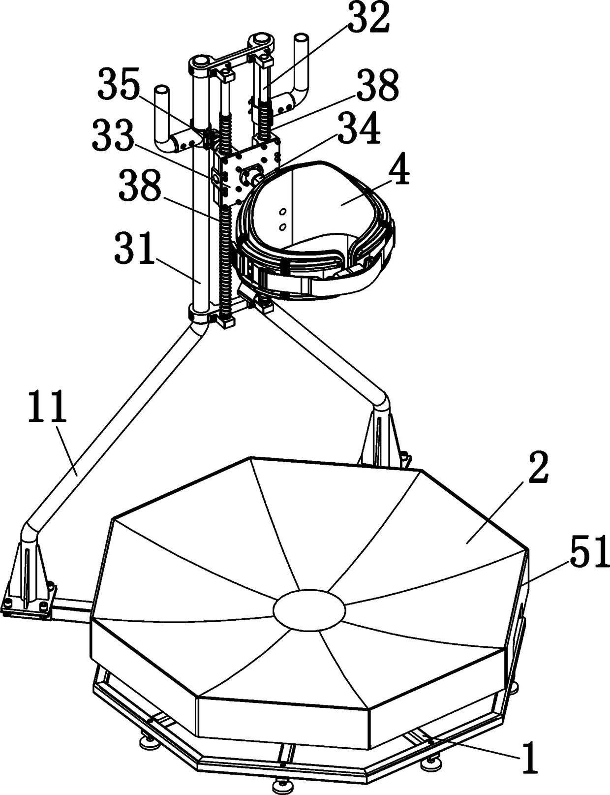
[0054] Embodiment 1: The infrared tracking frame 5 is a regular octagon. The infrared tracking frame 5 includes a first tracking frame 54 and a second tracking frame 55. The first tracking frame 54 and the second tracking frame 55 are arranged at intervals from each other. The first tracking frame The PCB boards 51 corresponding to 54 are all set as strip-shaped flat plates, and the PCB boards 51 corresponding to the second tracking frame 55 are all set as right-angled zigzags, that is, as Figure 7 As shown in the sawtooth-shaped bevel, the sawtooth of the bevel is as small as possible, and the shape and size of the sawtooth are equal. The jagged PCB board 51 can be spliced ​​by several PCBs through PCB connectors. The light-emitting tube 53 and the receiving tube 52 are both set perpendicular to the PCB board 51 .

Embodiment 2

[0055] Embodiment 2: The infrared tracking frame 5 is a regular octagon. The infrared tracking frame 5 includes a first tracking frame 54 and a second tracking frame 55. The first tracking frame 54 and the second tracking frame 55 are arranged at intervals from each other. The first tracking frame 54 and the corresponding PCB board 51 of the second tracking frame 55 are all set as a strip flat plate shape, and the light-emitting tube 53 and the receiving tube 52 on the PCB board 51 corresponding to the first tracking frame 54 are all arranged perpendicular to the PCB board 51, and the second The light-emitting tube 53 and the receiving tube 52 on the PCB board 51 corresponding to the tracking frame 55 are all set at an angle of 45 degrees with the PCB board 51; Figure 9 and Figure 10 Each light-emitting device shown is composed of two light-emitting tubes 53, and each receiving device is composed of two receiving tubes 52; the two light-emitting tubes 53 or the two receiving...

Embodiment 3

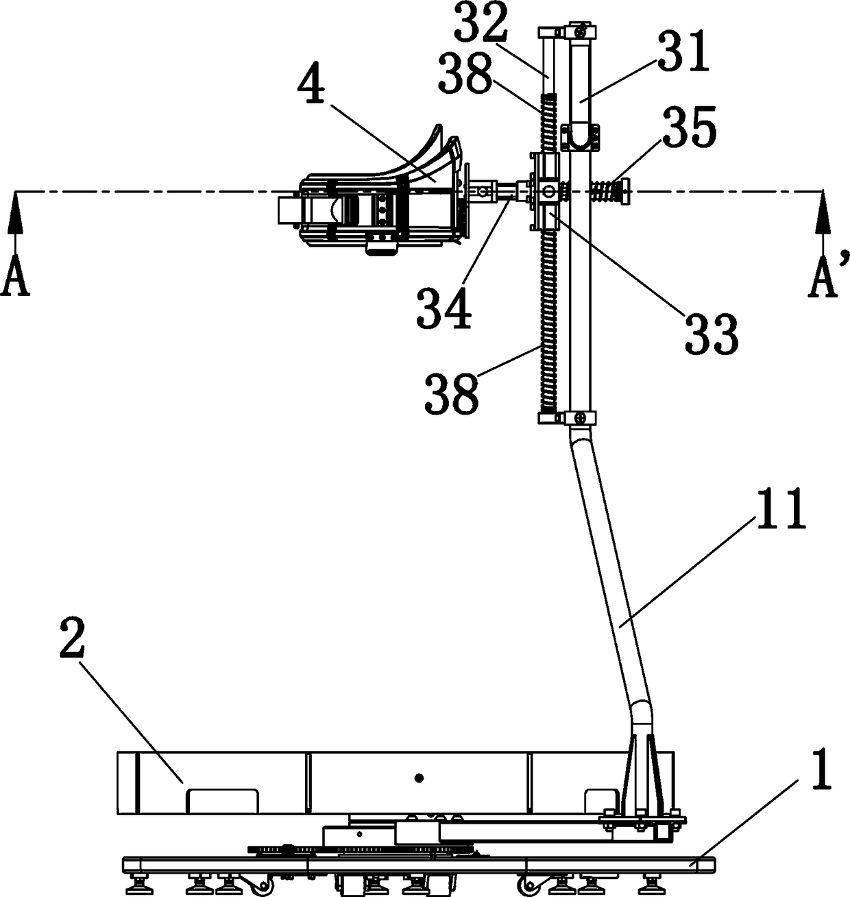
[0058] Embodiment 3: A limit spring 38 is arranged between the sliding limit plate 33 and the vertical support guide rail 32, the limit spring 38 is sleeved on the vertical support guide rail 32, and is fixedly arranged with the slide limit plate 33, the limit spring 38 The length is less than the length of the vertical support rail 32. The limit spring 38 mainly plays the role of buffering, and is used to protect the safety of the operator; further, the part of the limit spring 38 above the sliding limit plate 33 loses a part of the length (the length can be set according to the situation, such as according to different activities). The purpose is to prevent the operator from being restricted during the take-off process, but after jumping to a certain height, to prevent them from being injured and to protect the safety of the operator.


PUM


Abstract

The invention relates to an omni-directional mobile platform and a method for accurately tracking two-feet information based on the platform. The omni-directional mobile platform comprises a bottom frame which is provided with a running disc and a supporting frame, wherein the bottom frame is rotatably connected to the supporting frame; a waist ring is arranged at the side, facing the running disc, of the supporting frame; an infrared tracking frame is arranged at the edge of the top surface of the running disc; the infrared tracking frame is connected to a controller; the controller is connected to an angle encoder; and the angle encoder is arranged on the bottom frame; and the method comprises the following steps: acquiring information of the angle encoder on the infrared tracking frame;transforming orientation of two feet to a positive direction through rotation matrix transformation; respectively calculating coordinates and movement rates of left and right feet as well as a body direction in each frame of image; and implementing filtering, and accurately tracking the two-feet information. According to the omni-directional mobile platform provided by the invention, simulation that a user can feel that he is indeed moving in an infinite space can be achieved to the greatest extent, and corresponding moving is mapped into moving in an infinite space in a virtual scene; and inaddition, the omni-directional mobile platform provided by the invention has the characteristics of being simple in structure, small in volume, light in weight, simple to operate, convenient to use and the like.

Description

technical field [0001] The invention relates to the field of motion detection and control technology, the field of control, detection, realization and application of a rotating action platform based on virtual reality technology, and in particular to an omnidirectional mobile platform and a method for accurately tracking information on both feet based on the platform. Background technique [0002] Virtual display technology is a computer simulation system that can create and experience a virtual world. It uses a computer to generate a simulated environment. The user is immersed in the environment. Virtual reality technology takes head-mounted display technology as the core, supplemented by spatial positioning technology and other peripheral technologies to build a realistic virtual world. Walking input methods, such as keyboards and gamepads, the human body has adapted to using finger movements instead of legs; but for standing or moving virtual reality scenes, using tradit...

Claims


Application Information

Patent Timeline
Patent Type & Authority Applications(China)
IPC IPC(8): A63B26/00A63B71/06G06F3/01G06K9/62
CPCA63B26/00A63B71/0619G06F3/011A63B2071/0644A63B2225/50A63B2230/62G06F18/23213Y02E10/50
Inventor 王博
Owner HANGZHOU VIRTUAL AND REALITY TECH CO LTD
Why Eureka
Try Eureka