Supercharge Your Innovation With Domain-Expert AI Agents!

Automobile engine exhaust manifold parting and parting scheme thereof

A technology for automobile engines and exhaust manifolds, which is applied in the direction of casting molds, cores, and casting mold components. It can solve the problems of difficult control of product size, scrapping of castings, and high trial production costs, and achieve the improvement of process yield and production efficiency. , Improve the effect of manufacturing precision

Inactive Publication Date: 2018-07-20
KOCEL INTELLIGENT FOUNDRY IND INNOVATION CENT CO LTD
View PDF7 Cites 3 Cited by
  • Summary
  • Abstract
  • Description
  • Claims
  • Application Information

AI Technical Summary

Problems solved by technology

There are many sand cores produced by such a core making and molding process, the core assembly method is complicated, the process control requirements are cumbersome, and the skill level of the on-site workers is high.
At the same time, the size of the product is difficult to control, resulting in large size errors
Due to the influence of these factors, castings are often scrapped due to unqualified dimensions and other reasons. The scrap rate is as high as 35%, which also seriously affects the service life of the exhaust manifold and the overall performance of the car.
At the same time, if this process is used in the trial production of new products, due to the need to make molds, the cost of product trial production is high, and the production verification cycle is long, which is not conducive to the development of new products

Method used


Image

  • Automobile engine exhaust manifold parting and parting scheme thereof
  • Automobile engine exhaust manifold parting and parting scheme thereof
  • Automobile engine exhaust manifold parting and parting scheme thereof

Examples


Embodiment Construction

[0028] In order to illustrate the technical solution of the present invention more clearly, it will be described in detail according to the embodiments of the accompanying drawings. Obviously, the accompanying drawings in the following description are some embodiments of the present invention. For those of ordinary skill in the art, without paying Under the premise of creative work, other drawings can also be obtained based on these drawings.

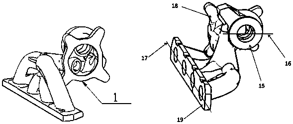
[0029] like figure 1 Shown is a schematic diagram of a three-dimensional model structure of an exhaust manifold for an automobile engine, wherein the exhaust manifold includes four exhaust branch pipes and two total exhaust pipes, and one end of the four exhaust branch pipes is arranged side by side Arranged on the flange surface 19 of the branch pipe, the other end is collected into the main pipe and then discharged through the first general exhaust pipe 15 and the second general exhaust pipe 18, and the central axis of the first gener...


PUM


Abstract

The invention discloses automobile engine exhaust manifold parting and a parting scheme thereof. According to parting and the parting scheme, a sand core and a sand mold of an exhaust manifold are used as a whole, an exhaust pipe is divided into three parts horizontally by using a first segmentation surface along the center of a first total exhaust pipe and a second segmentation surface along thecenter of a flange surface of a branch pipe, so that the most complex branch pipe structure can be formed on the sand mold of a middle sand mold 2 # at one time, the problems of difficulty in core assembling and poor in precision caused by independent core making and core assembling of the branch pipe are avoided, the mold assembling efficiency is improved by arranging a sprue cup fixing seat anda dead head positioning seat on the sand mold of an upper sand mold 3 #, positioning and supporting points are also provided for later casting, and in order to make mold assembling positioning convenient and the placed sand molds slide, the three parts of sand molds are correspondingly provided with mutual positioning structures. According to the technical scheme, the novel casting core splittingand parting method is provided, parting is carried out in the angle of integration of a mold and a core, the core assembling process and the mold core assembling process are avoided, the difficulty ofcore assembling is reduced, and the production efficiency and the product quality are improved.

Description

technical field [0001] The invention relates to the technical field of casting, in particular to the splitting technology of exhaust manifolds. Background technique [0002] like figure 1 The exhaust manifold shown in the automobile engine is mainly used to concentrate the exhaust gas of each cylinder into the total exhaust pipe. The operating temperature of the exhaust manifold is 750-1000°C, and the thickness of the pipe wall is 5mm-7mm; and the exhaust manifold is composed of multiple branch pipes, each branch pipe is in a curved structure, and finally merges into an outlet , the outlet is connected to the general exhaust pipe. [0003] In the existing production method, the wooden mold is mainly used for manual molding casting, and after the sand core is assembled into one body, the exhaust manifold blank is obtained after pouring molten iron and cooling. During the core assembly process, the accuracy of the core assembly is generally controlled by means of special fi...

Claims


Application Information

Patent Timeline
IPC IPC(8): B22C9/24B22C9/10B22C9/02B22C9/20B33Y80/00
CPCB22C9/24B22C9/02B22C9/103B22C9/108B22C9/20B33Y80/00
Inventor 孟庆文李朝东梁继亚李栋
Owner KOCEL INTELLIGENT FOUNDRY IND INNOVATION CENT CO LTD
Features
  • R&D
  • Intellectual Property
  • Life Sciences
  • Materials
  • Tech Scout
  • Unparalleled Data Quality
  • Higher Quality Content
  • 60% Fewer Hallucinations
Learn More