Receipt printing machine

A technology for printing presses and bills, applied in printing presses, rotary printing machines, printing and other directions, can solve the problems of inability to locate, reduce the processing quality and processing accuracy of invoices, etc., to avoid interference, accurately and effectively punch holes, and reduce speed. poor effect

Inactive Publication Date: 2019-07-23
重庆华康印务有限公司
View PDF8 Cites 0 Cited by
  • Summary
  • Abstract
  • Description
  • Claims
  • Application Information

AI Technical Summary

Problems solved by technology

[0003] When making multi-layer invoices, the punching operation is generally performed after stacking several layers of invoices, and then uniformly punch holes. When the position is adjusted and combined holes are processed, the position of the invoice after punching can no longer be adjusted, which reduces the processing quality and precision of the entire invoice, and the holes on each invoice cannot be adjusted during the printing process of the invoice. play a positioning role

Method used


Image

  • Receipt printing machine
  • Receipt printing machine
  • Receipt printing machine

Examples


Embodiment Construction

[0021] Further detailed explanation through specific implementation mode below:

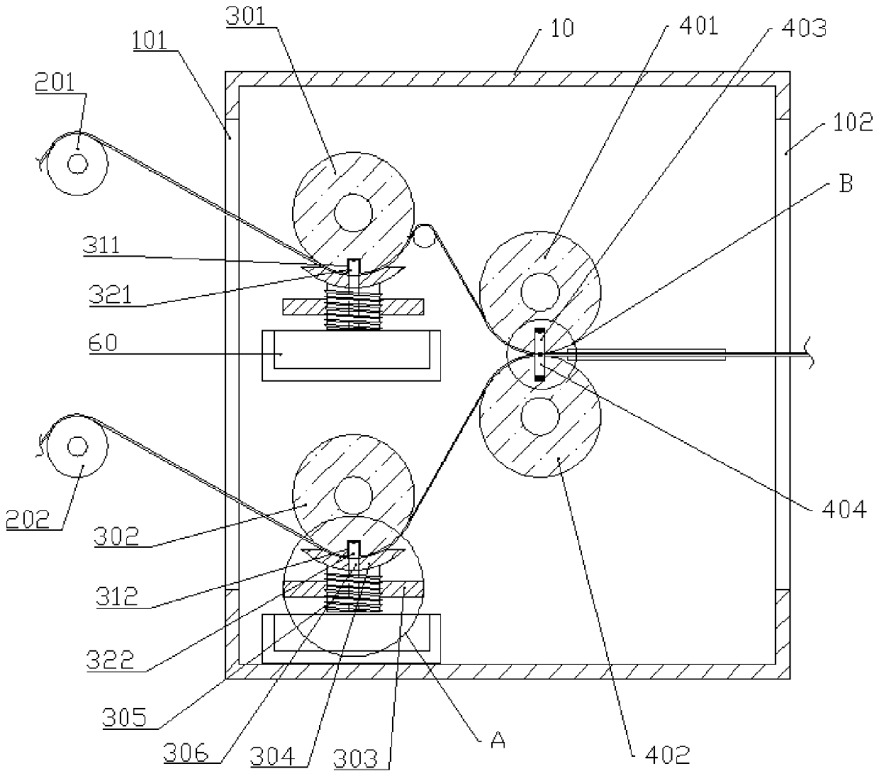
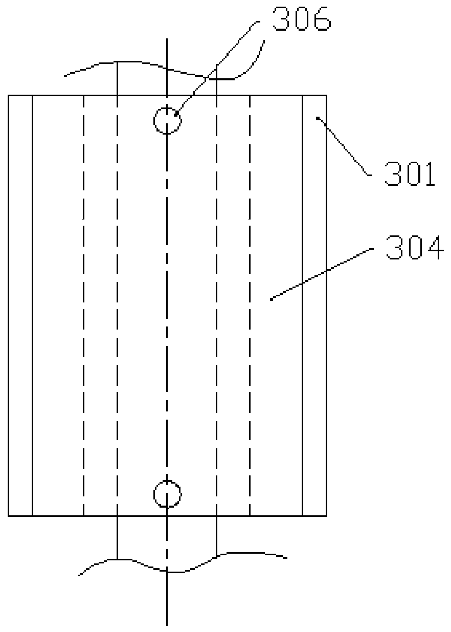
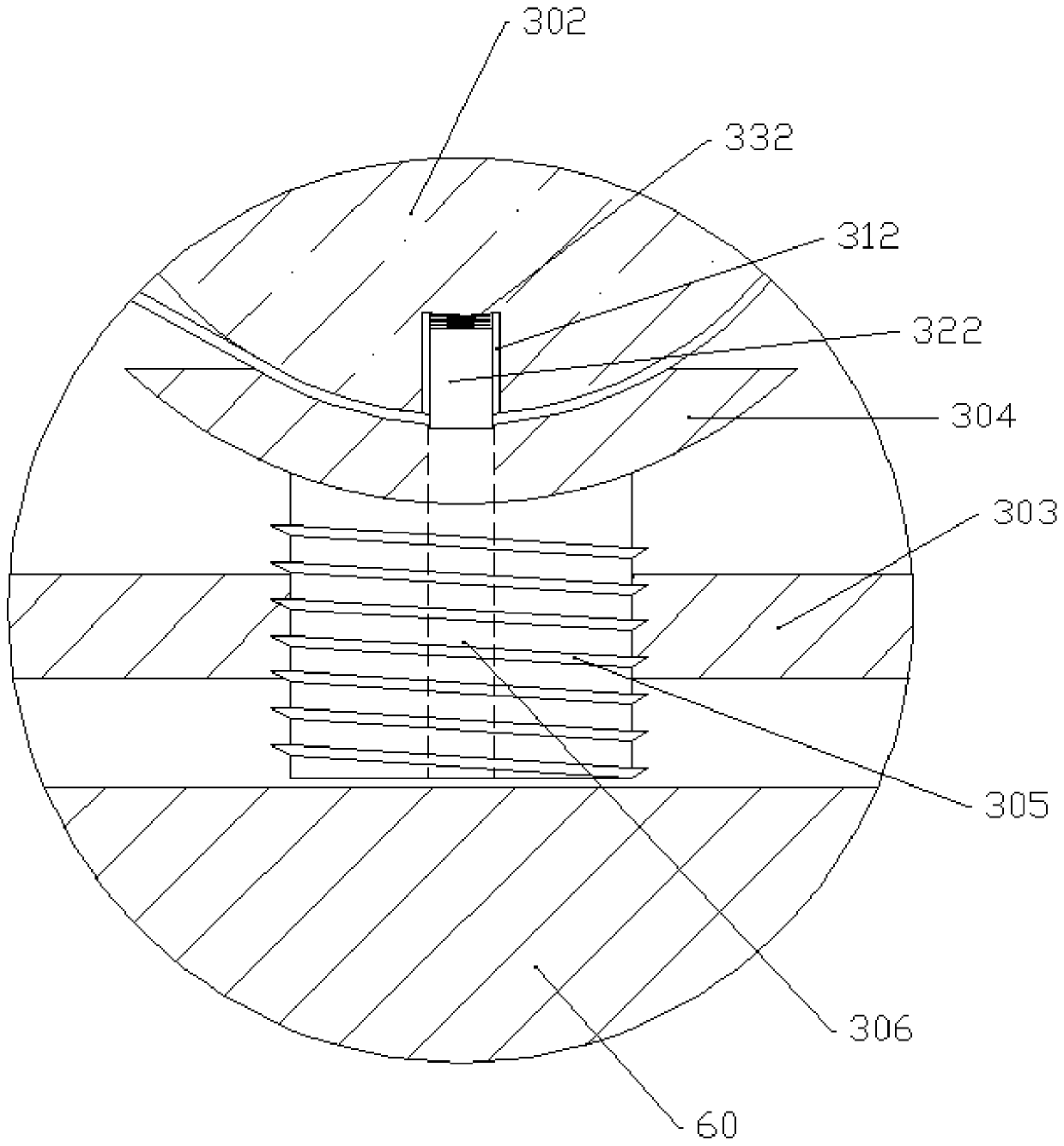
[0022] The reference signs in the accompanying drawings of the specification include: casing 10, inlet 101, outlet 102, first transmission wheel 201, second transmission wheel 202, first printing roller 301, first mounting hole 311, first punching knife 321 , the second printing roller 302, the second mounting hole 312, the second punching knife 322, the second tension spring 332, the fixing plate 303, the supporting plate 304, the adjusting rod 305, the through hole 306, the first conveying roller 401, the second Transmission roller 402, first push rod 403, second push rod 404, first connecting block 405, second connecting block 406, first pressing spring 407, second pressing spring 408, first pressing plate 501, second pressing Tightening plate 502 , glue outlet plate 503 , glue outlet 504 , collection frame 60 .

[0023] The embodiment is basically as attached figure 1 , attached figure 2 ...


PUM


Abstract

The invention relates to the field of printing, and in particular, discloses a bill printing machine. The bill printing machine comprises a detecting mechanism; the detecting mechanism comprises a first conveying roller, a second conveying roller, a first ejector rod, a second ejector rod and a circuit; the first ejector rod is elastically mounted on the side surface of the first conveying roller;the second ejector rod is elastically mounted on the side surface of the first conveying roller; the end, far from the first conveying roller, of the first ejector rod can be contacted with the end,far from the second conveying roller, of the second ejector rod; the diameters of the first printing roller, the second printing roller, the first conveying roller and the second conveying roller areconsistent; an indicating lamp is arranged in the circuit; an electric conducting first connecting block is arranged at the end, far from the first conveying roller, of the first ejector rod; an electric conducting second connecting block is arranged at the end, far from the second conveying roller, of the second ejector rod; and the first connecting block can be contacted with the second connecting block. The bill printing machine can perform punching positioning on multiple layers of bills before merging to improve the bill processing precision.

Description

technical field [0001] The invention belongs to the field of printing, and in particular relates to a bill printing machine. Background technique [0002] Invoices and other bills are business vouchers issued and received by units and individuals commonly used in our daily life when buying and selling goods, providing or receiving services, and engaging in other business activities. The invoice has continuity and uniqueness. Invoice printing is a rigorous and high-tech work. In general invoice processing, it is necessary to punch holes on the edge of the invoice. The punched invoice is easy to place when in use. In small printers, the printer can position the holes on the invoice, and it can be loaded in a stack on the receipt printer and continuously fed for uninterrupted printing. [0003] When making multi-layer invoices, the punching operation is generally performed after stacking several layers of invoices, and then uniformly punch holes. When the position is adjusted...

Claims


Application Information

Patent Timeline
Patent Type & Authority Patents(China)
IPC IPC(8): B41G7/00B41F19/00
CPCB41F19/004B41G7/00
Inventor 吴仁本
Owner 重庆华康印务有限公司
Why Eureka
Try Eureka