Assembly structure of assembly-type concrete member

A technology for assembling structure and concrete, applied in the direction of structural elements, building components, building reinforcements, etc., can solve the problems of large reinforcement area, difficult control of quality standards, difficult operation, etc. Connection quality, the effect of improving the contact area

Active Publication Date: 2018-07-20
HEFEI CONSTR ENG GRP
View PDF5 Cites 18 Cited by
  • Summary
  • Abstract
  • Description
  • Claims
  • Application Information

AI Technical Summary

Problems solved by technology

The prefabricated concrete structure refers to the concrete structure assembled by prefabricated concrete components through a reliable connection method, and then the prefabricated concrete structure is integrated with the post-cast concrete and cement-based grouting materials on site to form an integrated concrete structure. Its core And the difficulty is the quality of the steel bar connection, that is, the existing technology and process are difficult to guarantee the coaxial butt joint of the steel bars to be connected. At present, non-shrinkage or micro-expansion cement-based grouting materials are usually poured into the semi-grouting or full-grouting sleeves to realize prefabricated components. The connection between them, but the existing construction technology is difficult to ensure that the sleeve is filled with grouting material, and it is difficult to ensure that the grouting is dense, and there is no effective technical means to detect the grouting density in the specific engineering construction. Therefore, the prefabricated building The development and use in areas with high seismic fortification requirements are limited. Therefore, in order to realize the universal applicability of prefabricated construction technology, it is necessary to address the above problems and improve the connection structure and construction technology in a targeted manner.
[0003] Due to the large geometric size of the full-grouting sleeve, the grouting workload is large, the construction is difficult, and the reinforcement area around the connection node is large. At present, half-grouting sleeves are commonly used in engineering, and the widely used half-grouting sleeves are cast iron. One end of the sleeve is directly connected to the steel bar bolt, and the other end is directly connected by grouting. Therefore, at the construction site, the ribs on the steel bar must be stripped clean, and one end of the steel bar is cold-rolled into wire, and then threaded with the half-grouting sleeve. The disadvantages of the connection method are: 1) the on-site thread processing process is complicated, and the quality standard is difficult to control; 2) when the thread connection is carried out on the construction site, a torque wrench must be used, which is difficult to operate; 3) the steel bar inserted into the grouting sleeve The length and threaded connection quality control must meet the requirements of national standards and regulations, and it is extremely difficult to achieve a high pass rate; 4) In the currently disclosed technology, the semi-grouted connection structure mainly adds ribs from the non-grouted connection section and the side wall of the grouted sleeve. To improve the strength of the connection part of the fabricated concrete member, so that the wall of the sleeve is thicker and the self-heavy
In the prior art, it is generally adjusted manually by tapping with a wrench or bending with pliers. The adjustment process is noisy and the precision is low.

Method used


Image

  • Assembly structure of assembly-type concrete member
  • Assembly structure of assembly-type concrete member
  • Assembly structure of assembly-type concrete member

Examples


Embodiment 1

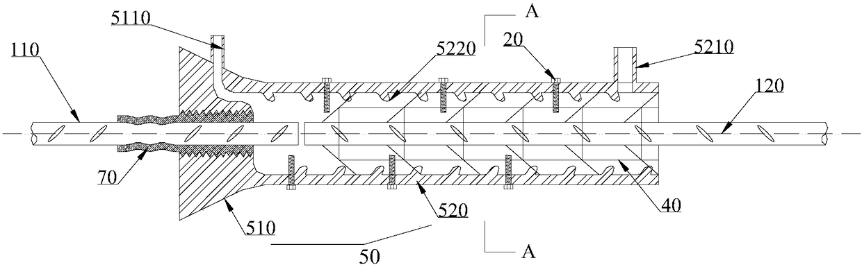
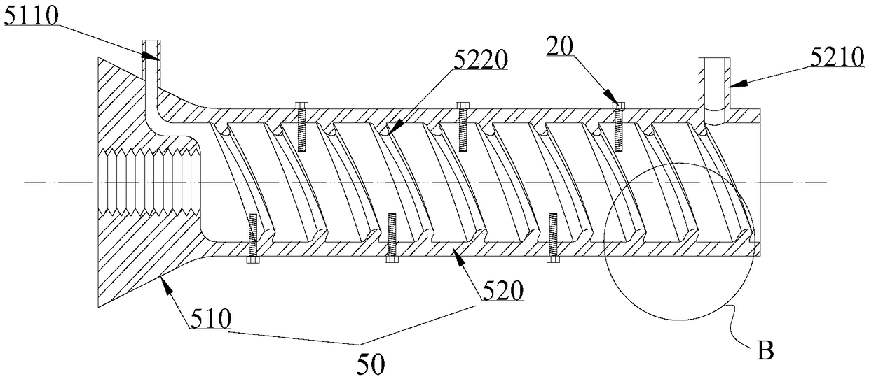
[0058] Such as figure 1 , figure 2 , image 3 As shown, an assembly structure of a prefabricated concrete member includes a sleeve 50, a steel pipe transition section 70, and a self-locking steel skeleton 40;

[0059] The sleeve 50 includes a non-grouting connection section 510 and a grouting connection section 520; the non-grouting connection section 510 is a conical cylindrical structure, and the grouting connection section 520 is a cylindrical structure; the small diameter end of the non-grouting connection section 510 and the grouting connection section 520 One end of the connection is connected, and the connection is rounded. A grouting hole 5210 is provided at the end of the grouting connection section 520 away from the non-grouting connection section 510, and a vent hole 5110 extends from the other end to the non-grouting connection section 510. The vent hole 5110 can be specifically: A first vertical and then horizontal air hole is set on the cone, and the air hole...

Embodiment 2

[0067] A method for processing an assembly structure of a prefabricated concrete component: comprising the following steps:

[0068] Step 1. Grouting sleeve 50 processing

[0069] The grouting sleeve 50 is processed by casting and integrally formed; one end is internally threaded, and multiple mounting holes are opened on the cylinder for standby;

[0070] Step 2. Steel pipe transition section 70 processing

[0071] Select a steel pipe with a suitable length and thickness as the steel pipe transition section 70; one end of the steel pipe transition section 70 is externally threaded for standby;

[0072] Step 3. Self-locking steel skeleton 40 processing

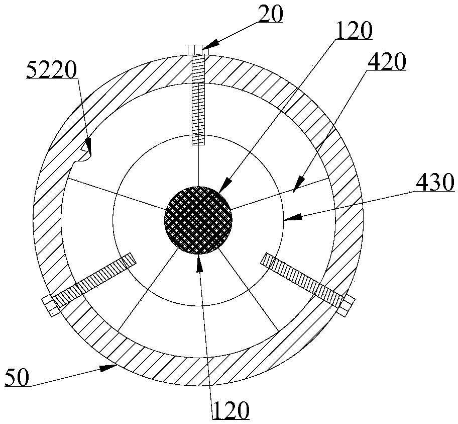
[0073] First, a plurality of longitudinal guiding steel bars 410 and a plurality of circumferential fixed steel rings 430 are welded into a cylindrical keel, and then a plurality of oblique steel branches 420 are radially and obliquely welded on multiple annular sections of the keel to form inner barbs 4210 and Outer barb 4...

Embodiment 3

[0077] A processing method for fabricated concrete components, comprising the following steps:

[0078] Step 1. Binding of reinforced skeleton of prefabricated concrete members

[0079] One end of the first to-be-connected steel bar 110 is bound and fixed with other steel bars to form a reinforced skeleton of a prefabricated concrete member. The other end of the first to-be-connected steel bar is inserted into the rolling section 710 of the steel pipe transition section 70, and the steel pipe transition section 70 is realized by rolling machinery. The connection with the first steel bar 110 to be connected, so that the self-locking semi-grouting sleeve 50 is pre-installed in the reinforced skeleton of the prefabricated concrete member;

[0080] Step 2. Pouring of prefabricated concrete elements

[0081]Connect the plastic pipe 80 to the grouting hole 5210 and vent hole 5110 on the side wall of the sleeve 50 and lead it out of the component formwork, then the concrete placing ...


PUM


Abstract

The invention provides an assembly structure of an assembly-type concrete member. A sleeve comprises a non-grouting connection section and a grouting connection section. A steel skeleton comprises inner barbs and outer barbs, the diameter of a passage defined by the multiple inner barbs is smaller than that of a second to-be-connected steel bar, and the outline diameter defined by the outer barbsis larger than the diameter of an inner cavity of the grouting connection section. An alignment device comprises lower supports and upper supports which are both electromagnets, the same magnetic poles of the upper supports and the lower supports are opposite, and the upper supports and the lower supports are connected in the same circuit in series. All parts of the grouting sleeve are machined and manufactured correspondingly and then assembled, mass production is achieved, and the quality of all the parts is easy to control; connection of the grouting sleeve and a steel pipe transition section is operated by machines in a factory, the threaded connection quality is easy to control, the self-locking type steel skeleton is adopted, thus the purpose of pulling preventing is achieved, and shock resistance is improved; through the principle of magnetic levitation, fast and accurate centering of the steel bars of upper and lower concrete member bodies is achieved, so that the time and labor are saved; and through the series-connection circuit, the same magnetic forces of a plurality of supporting mechanisms can be achieved, and stable supporting is guaranteed.

Description

technical field [0001] The invention belongs to the field of prefabricated building construction, in particular to an assembly structure of prefabricated concrete components. Background technique [0002] From the perspective of the global environment, it is imperative for the construction industry to develop into prefabricated construction. The continuous progress of prefabricated concrete building construction technology provides a technical basis for improving the performance of prefabricated prefabricated structures and realizing the housing industry. The prefabricated concrete structure refers to the concrete structure assembled by prefabricated concrete components through a reliable connection method, and then the prefabricated concrete structure is integrated with the post-cast concrete and cement-based grouting materials on site to form an integrated concrete structure. Its core And the difficulty is the quality of the steel bar connection, that is, the existing tech...

Claims


Application Information

Patent Timeline
Patent Type & Authority Applications(China)
IPC IPC(8): E04C5/16
CPCE04C5/165E04B1/4114E04B1/043E04B1/4121
Inventor 郑志涛刘国福涂刚要朱海生王玉国
Owner HEFEI CONSTR ENG GRP
Why Eureka
Try Eureka