Depth imaging super-resolution microscopic imaging system

A microscopic imaging and super-resolution technology, applied in microscopes, analytical materials, material excitation analysis, etc., to achieve the effects of low photobleaching and phototoxicity, high imaging quality, and correction of aberrations

Inactive Publication Date: 2018-07-20
CHINA JILIANG UNIV
View PDF7 Cites 18 Cited by
  • Summary
  • Abstract
  • Description
  • Claims
  • Application Information

AI Technical Summary

Problems solved by technology

[0006] The present invention aims at the aberration problem of sample depth direction scanning existing when the existing super-resolution micros

Method used


Image

  • Depth imaging super-resolution microscopic imaging system

Examples


Embodiment Construction

[0049] The present invention will be described in detail below in conjunction with the accompanying drawings, but the present invention is not limited thereto.

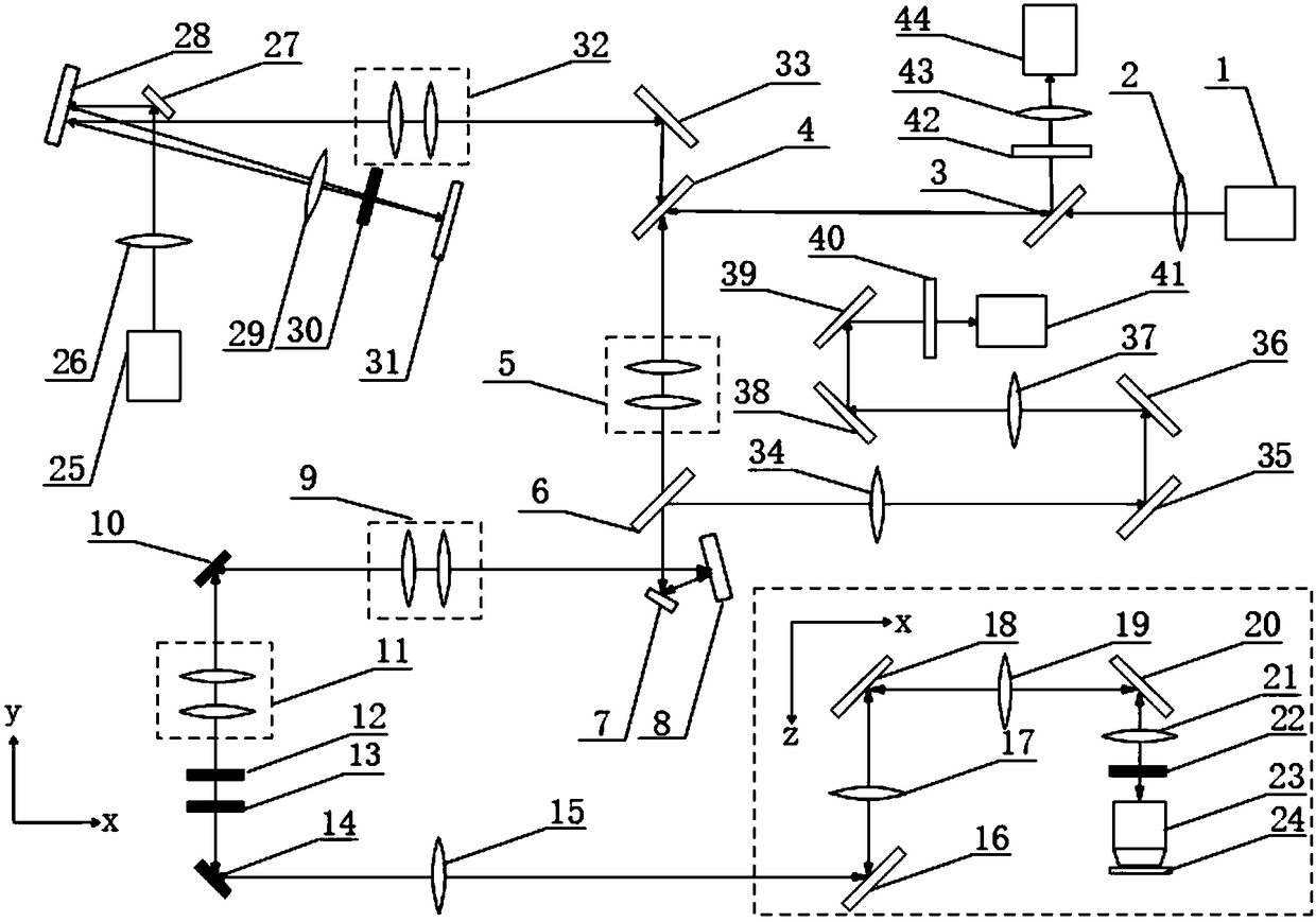
[0050] like figure 1 Shown is an optical path diagram of an embodiment of a depth imaging super-resolution microscope system structure of the present invention, the system of this embodiment includes:

[0051] The first laser 1, the first lens 2, the first dichroic mirror 3, the second dichroic mirror 4, the first telescopic system 5, the third dichroic mirror 6, the first mirror 7, the deformable mirror 8, the first mirror Two telescopic system 9, X-axis scanning galvanometer 10, third telescopic system 11, half-wave plate 12, first quarter-wave plate 13, Y-axis scanning galvanometer 14, second lens 15, second reflector Mirror 16, the third lens 17, the third reflection mirror 18, the fourth lens 19, the fourth reflection mirror 20, the fifth lens 21, the second quarter wave plate 22, the microscope objective lens 2...


PUM

PropertyMeasurementUnit
Wavelengthaaaaaaaaaa

Abstract

The invention discloses a depth imaging super-resolution microscopic imaging system. The depth imaging super-resolution microscopic imaging system includes a first laser, a first lens, a first dichroscope, a second dichroscope, a second laser, a sixth lens, a phase modulation assembly, a third dichroscope, a deformation reflector, an X axis scanning vibrating mirror, a phase compensation assembly,a Y axis scanning vibrating mirror, a vertical optical path refraction matching unit, a second quarter wave-plate, a microscopic object lens, a sample table, a horizontal optical path refraction matching unit, a first optical filter, a wavefront sensor, a second optical filter, a tenth lens and an imaging device. By means of the two-photon effect, by compensating the fluorescent wavefront phase change through the wavefront sensor and the deformation reflector, by combining with movement of the sample table in the Z axis direction, the depth imaging super-resolution microscopic imaging systemcan realize three-dimensional depth imaging while correcting the aberration caused by the samples, thus being relatively higher in the imaging quality.

Description

technical field [0001] The invention relates to the field of optical microscopic imaging, in particular to a depth imaging super-resolution microscopic imaging system. Background technique [0002] In a conventional optical microscopic imaging system, due to the diffraction effect of optical components, the light spot formed on the sample after the parallel incident illumination light is focused by the microscopic objective lens is not an ideal spot, but a spot with a certain size. Diffraction spot, according to Abbe's diffraction limit formula, the diameter of the smallest spot that can be focused by visible light is about 200nm. In 1994, German scientist S.W.Hell first proposed STED super-resolution microscopy imaging technology, which surpassed the diffraction limit and achieved a spatial resolution of 30 nanometers in 2006. This outstanding work won him the Nobel Prize in Chemistry in 2014. prize. [0003] The basic idea of ​​STED super-resolution is to use the stimula...

Claims


Application Information

Patent Timeline
IPC IPC(8): G02B27/58G02B26/10G02B21/36G01N21/64
CPCG01N21/6458G02B21/365G02B26/101G02B27/58
Inventor 李旸晖李雨雪周辉刘小煜夏成樑
Owner CHINA JILIANG UNIV
Why Eureka
Try Eureka