Furnace drying system of hot-blast furnace, furnace drying system of blast furnace and furnace drying method

A hot blast stove and oven technology, applied in blast furnaces, blast furnace details, blast furnace parts, etc., can solve the problems of low pressure in the furnace, small flue gas flow, poor flue gas distribution uniformity, etc., to avoid burst damage and uniform atmosphere. Good performance, good drying effect

Pending Publication Date: 2018-07-24
QINHUANGDAO QINYE HEAVY IND
View PDF4 Cites 7 Cited by
  • Summary
  • Abstract
  • Description
  • Claims
  • Application Information

AI Technical Summary

Problems solved by technology

Before the relocation and new blast furnace is put into operation, the blast furnace and its associated hot blast stove need to be heated and baked. Before the first blast furnace is put into operation, the main burner of the hot blast stove cannot complete the firing and supply air to the blast furnace because there is no blast furnace gas on site. blast furnace
Or there is no blast furnace gas produced due to maintenance, shutdown and other reasons
[0003] In order to solve the above problems, an oven burner can be installed directly on the blast furnace body, but the distribution of the flue gas burned in this way is poor in the furnace, the flue gas flow rate is small, and the furnace pressure is low during the oven, which is harmful to the blast furnace. The baking of the brickwork at the bottom of the hearth cannot meet the temperature requirements, especially if it exceeds 2000m 3 The volume of the blast furnace is basically unable to meet the process requirements of the furnace curve

Method used


Image

  • Furnace drying system of hot-blast furnace, furnace drying system of blast furnace and furnace drying method
  • Furnace drying system of hot-blast furnace, furnace drying system of blast furnace and furnace drying method

Examples


Embodiment Construction

[0040] The present invention will be described in further detail below in conjunction with the accompanying drawings and specific embodiments, but not as a limitation of the present invention.

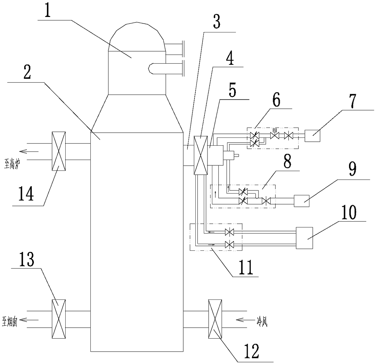
[0041] figure 1 It is a structural schematic diagram of the hot blast furnace oven system of the present invention. Such as figure 1 Shown, the hot blast furnace oven system of the embodiment of the present invention comprises:

[0042] The hot blast stove 2 has a cold air inlet, a hot air outlet, a flue gas outlet and a vault manhole 3;

[0043] The combustion shut-off valve 4 is used to connect with the vault manhole 3 of the hot blast stove 2, and the combustion shut-off valve 4 has a water-cooled structure;

[0044] The oven burner 5 is connected with the combustion cut-off valve 4;

[0045] The gas supply mechanism is connected with the oven burner 5 to provide gas for the oven burner 5;

[0046] The supporting gas supply mechanism is connected with the oven burner 5, and pro...


PUM


Abstract

The invention discloses a furnace drying system of a hot-blast furnace, a furnace drying system of a blast furnace and a furnace drying method. The furnace drying system of the hot-blast furnace comprises a hot blast furnace provided with a cold air inlet, a hot air outlet, a smoke outlet and a vault manhole, a combustion cut-off valve which is used for being connected with the vault manhole of the hot blast furnace and is provided with a water cooling structure, a furnace drying combustor connected with the combustion cut-off valve, a gas supply mechanism which is connected with the furnace drying combustor and is used for supplying gas to the furnace drying combustor, a combustion-supporting gas supply mechanism which is connected with the furnace drying combustor and is used for supplying combustion-supporting gas to the furnace drying combustor, and a cooling water supply mechanism which is connected with a water cooling structure of the combustion cut-off valve and is used for supplying cooling water to the combustion cut-off valve. According to the furnace drying system of the hot-blast furnace, the furnace drying system of the blast furnace and the furnace drying method disclosed by the invention, under a situation of not using a main combustor of the hot blast furnace, the blast furnace is subjected to furnace drying, and the problem of the furnace drying on the blast furnace under a situation of no blast furnace gas of a newly-built blast furnace is solved.

Description

technical field [0001] The invention relates to a blast furnace oven equipment, in particular to a hot blast furnace oven system, a blast furnace oven system and an oven method. It belongs to the field of metallurgy. Background technique [0002] Blast furnace baking is usually completed by means of hot blast furnace firing and air supply, and the hot blast stove firing is completed by burning blast furnace gas through the main burner on the top; Blast furnace gas is a by-product combustible gas in the process of blast furnace ironmaking. It is the main fuel for the main burner of blast furnace hot blast stove. Most of the main burners of hot blast stove can only burn blast furnace gas. But in some cases, there is no blast furnace gas for the main burner of the hot blast stove to work. For example, as the country intensifies efforts to relocate industrial enterprises from cities, more and more iron and steel enterprises have relocated their blast furnaces through capacity ...

Claims


Application Information

Patent Timeline
Patent Type & Authority Applications(China)
IPC IPC(8): C21B9/00C21B7/00C21B5/00
CPCC21B5/00C21B7/00C21B9/00
Inventor 陈晓光杨树新郁景民郜宏亮张闯范博文翟树兵张博罗会涛
Owner QINHUANGDAO QINYE HEAVY IND
Why Eureka
Try Eureka